Unit 2: Grade 11/12 Technological Design - Robotics - Engineering Communication
This unit will focus on technical sketching, communication drawing standards, design process, CAD model and drawing, and design implementation.
Course Units and Descriptions
Use this table for an overview and navigate to each of the course unit pages.
| Unit | Description |
|---|---|
| Review course outline for more details | |
| 1 | Careers & Safety- Intro, computers, organization, and research career |
| 2 | Engineering Communication- Technical sketching, ortho-ISO, custom ortho, and robot design |
| 3 | Structure and Materials- Materials & measurement, joints, frame, and 3D model |
| 4 | Driven Mechanisms- Gears, gearbox to wheel, drive train, and 1st function |
| 5 | Functions and Integration- Body base, pneumatics, 2nd and 3rd function |
| 6 | Robot Assembly- Robot build, function supports, drawings and presenting |
| 7 | Marketing and Portfolio- Web authoring, portfolio and presentation |

Unit Content Activity Quick Links, Click to Jump to Specific Activity!
 Unit 2, Act. 1: Technical Sketching
Situation:
A class of students interested in the field of Engineering have taken a course to find out what Technology Design is all about. Coming up with solutions is what Engineers do on a daily bases. How they communicate those ideas is critical and one of those ways is with technical sketching.

Problem/Challenge:
Practice your sketching techniques with sketching practice assignments
- Basic Sketching and shapes
- Selecting front view of an object
- Orthographic Sketching
- Dimensioning and Standards
- Isometric Sketching
Related assignments found below in the Create & Construct section.
Investigation/Ideas:
Communicating your ideas is key for Engineers and is a critical skill to learn. Technical sketching is used in all kinds of situations. Thumbnails are where ideas initially start... some of the greatest ideas started on a napkin in a restaurant for example. Full size sketches take a little more work and formality to the steps of creating a clean technical sketch.

Below are several resources you may check out all related to technical sketching:
- The Importance of Sketching
- Sketch-A-Day project-38
 Sketch-A-Day project-44
- Learning To Draw Buildings
 Engineering Graphics
- Sketching
- Drawing Fundamentals
- Thumbnail Sketching
- Technical Sketching and DWG
- Process of Tech-sketches
- Principles - DWG & sketches
- Third Angle Projection
- Orthographic Projection
- Isometric Projection theory
- Isometric sketching tut.
- The Process of Architecture
 Multi-view Mechanical DWGs
- Engineering Drawing
- Subtractive sketching 21.33
- Additive sketching 14.02
Sketching Tips
Below are some tips that you can use when sketching objects with orthographic views and dimensioning
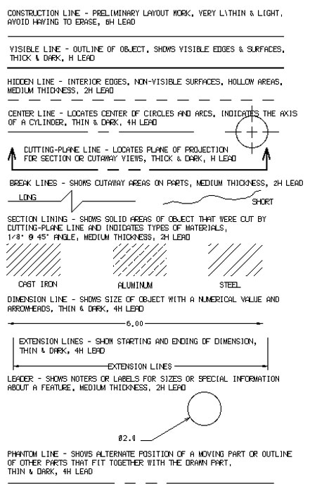
Line Types

Arrows
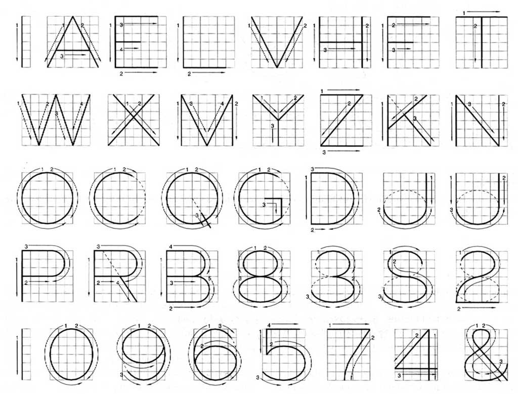
Lettering
Dimensions 1
Dimensions 2

Key Points to keep in mind while sketching
- lettering sizing is generally 6 mm for titles, 3 mm for normal
- Using two parallel lines will ensure consistency and straightness of lettering
- speed will smooth out your lines (remember bicycle analogy)
- ensure circles are large (full size, using up most of the space)
- create circles using cross-hairs first, then marking space from centre, then smooth circle hitting all space marks
- try to keep page straight to practice different directions
- include all text and sketching for full marks,some forget to fill in the two key points below the title and reference
- don't erase, just keep practicing and use back or another sheet if necessary
- start a new sheet and staple all of your practice sheets together, with final (best one to be marked) at the front
- don't worry so much about stopping exactly at each corner of objects
- practice on back and asterisk the ones you would rather the instructor mark
- making shapes a light construction line for the base line will help with shape creation
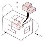
- for complex shapes, use additive or subtractive sketching methods

Common Mistakes When Sketching Orthographic Views of Objects
Some common mistakes students make when sketching objects for orthographic views are:
- Not selecting the correct front view, understand and check all three rules for selecting front view
- Sketching relative sizes to dimensions of object or object features
- Not aligning feature details in each view, using construction lines if necessary
- Ensure arrow sizes are thinner, ratio of 2:3 - width to length, and ensure they are touching extension lines
- Line weights are not correct, remember construction lines are light and thin to show build of sketch, object lines are thick dark showing object views, dimension lines area thin and with medium weight with open gap in centre for dimension always written the same direction

Selecting Front View
When deciding which view is to be used for the front view, three rules are used to determine this. You must look at the object you are going to draw or sketch and decide which view shows the:
- The most detail
- Least amount of hidden lines
- Length across the page (as layout is usually in landscape format)
Practice View Selection
The following show a process of deciding on what the front view of an object is by using a quick prototype for spacial recognition if needed (in time, you can practice visualizing the different views in your head), then looking at possible views based on the three rules for selecting a front view to narrow down to a final decision on the front view
Spacial Rec.
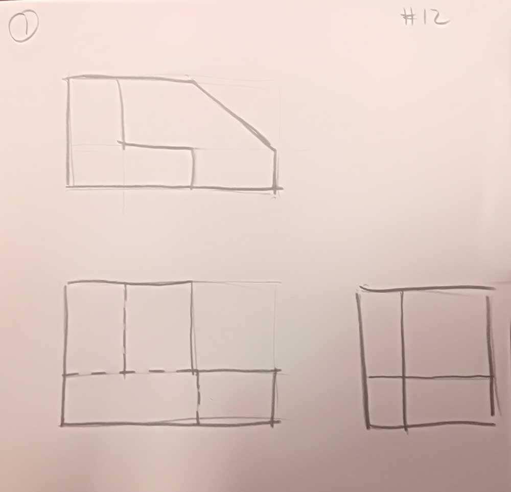
1st possibility.
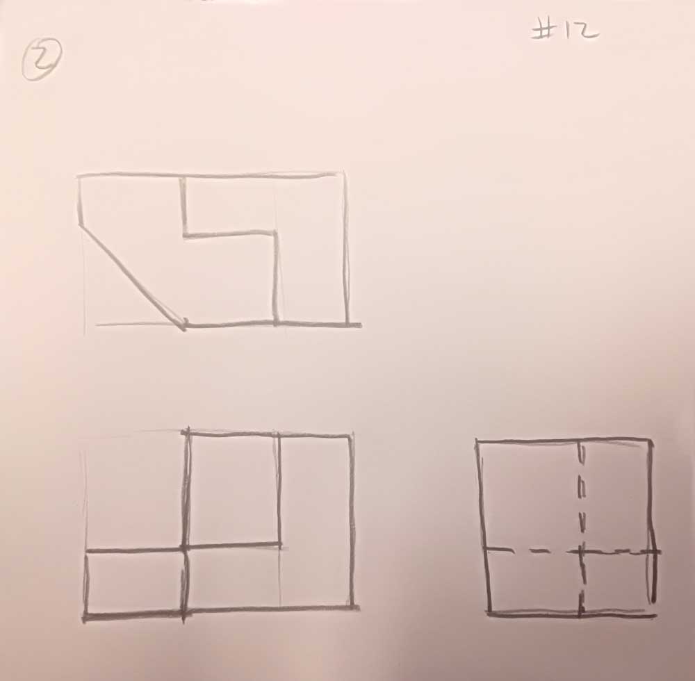
2nd possibility
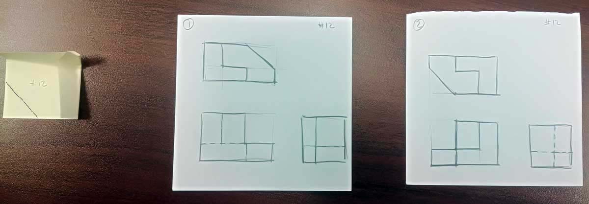
Visualize/prototype for front view
Looking at both possibilities above (small thumbnails), one more important point to keep in mind, the front view takes precedence in relaying the shape detail with respect to silhouette shape and showing less hidden lines when possible. In the case of sample above, less hidden lines in the 2nd possibility is the clear choice for the front view.
Once you have established the front view then you can be confident to sketch out the full page with the features, equal view spacing, dimensions, and isometric to create your ortho sketch as shown below.
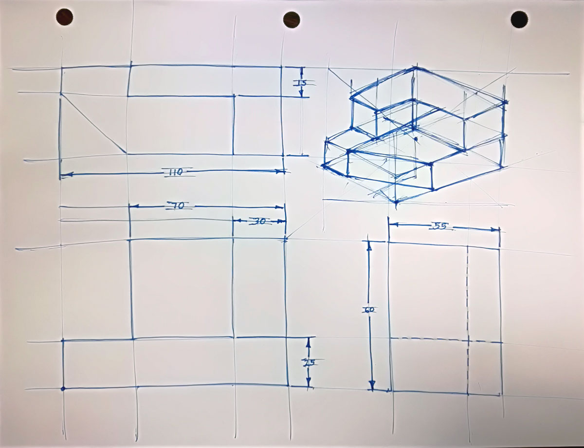
Layout & features
Object & Header
Orthographic Sketches
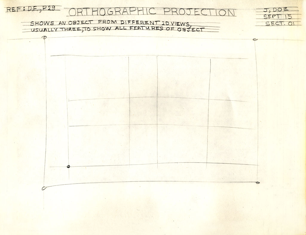
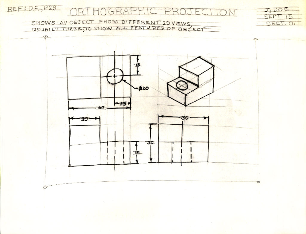
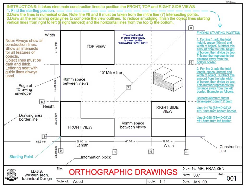
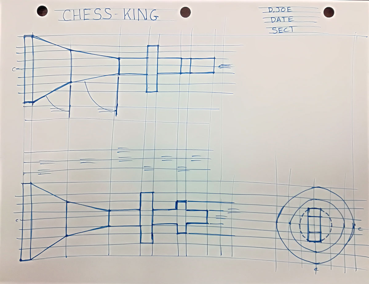
The following three images are showing a third angle projected orthographic sketch and dimensions would look like using a standard "step block" shape with a circular hole going through the center of the bottom step.
Below, ![]() 1 - 7 is a orthographic note, shown in order of creation, from blocking in views to finished sketch. After, labels that are not normally included in a finished sketch is for your detailed information about the process, parts of the sketch, sizing, and locations of specific components sketched.
1 - 7 is a orthographic note, shown in order of creation, from blocking in views to finished sketch. After, labels that are not normally included in a finished sketch is for your detailed information about the process, parts of the sketch, sizing, and locations of specific components sketched.
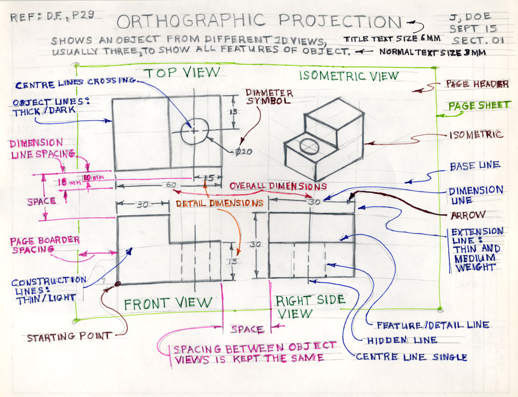
7, Labels done
(only for info)
Orthographic Sketching Major Steps
By following these steps in order, will give you best results in a quick and efficient manner:
- Start by visualizing the approximate shape and size of your front view, and how much space needed for dimensioning
- Block in your views using construction lines starting with your front view, then your spacing, top view and right side view leaving room for your isometric view
- Block in your major view features using construction lines so that they will all align with each other
- Darken your object lines for all views including outline, features, and hidden lines
- Start dimensioning using construction lines to add ladder distances out from view envelopes 10 mm and 8 mm thereafter
- Ensure you are following dimensioning rules/standards in placement, locations, alignment, and spacing
- Create extension and dimension lines along with small thin arrows 2 mm thick by 3 mm long with dimensions 3 mm high
- Last, create your isometric by blocking in a wired cube/rectangle using additive/subtractive construction build sketch process with construction lines, then darken your object lines
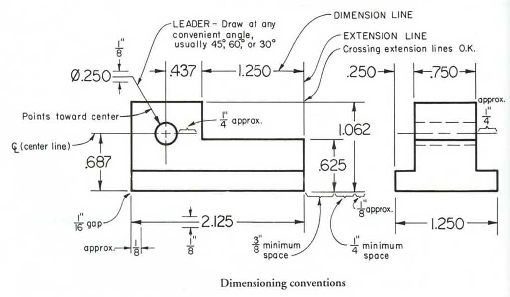
![]() Some points to keep in mind when dimensioning:
Some points to keep in mind when dimensioning:
- Minimize the amount of dimensions to keep less cluttered
- Show overall and detailed dimensions to show feature locations and size
- Overall dimensions should be furthest out with detail dimension in between object view and overall
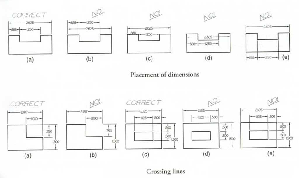
- Avoid placing dimensions on the actual view
- Avoid placing dimensions where dimension lines cross extension lines
- Extension lines may cross each other freely
- Extension lines may cross the lines of the drawing to dimension features properly
- Stay inside the envelope as much as possible
- Space the dimensions about 3/8" or 10 mm from the object and 1/4" or 6 mm apart thereafter
- Dimension on view that shows the feature best
- Draw all arrowheads about 1/8" or 3 mm long and very narrow
For a look back to Tech Design intro, check out The Ortho Step Block in Detail for more support and informaiton.
Create/Construct:

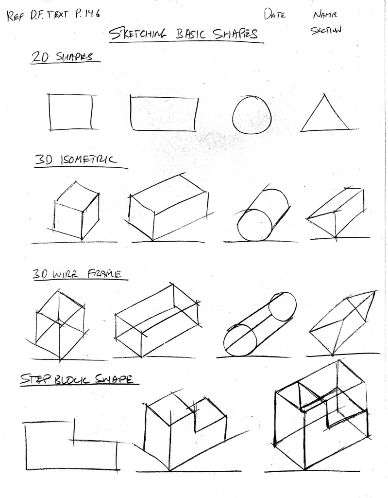
Sketching Shapes
Sketching Basic Shapes
The following technical sketching shape assignment is to be practiced in class, digitized, submitted for check, before moving on to the next sketch assignment. You will need blank paper and a pencil to complete sketching shapes assignment. Keep in mind the following:
- Line weights - light construction for layout, medium for dimensions, and heavy thick for object lines
- technical sketching techniques - wrist for fine detail, elbow for medium sized features, and whole arm/body for larger longer features
- layout page -including header, centering, object placement, and equal spacing - leave on page for evidence and marks
- sketching process - two stage sketch building, ISO base lines, parallel lines, additive, and subtractive drawing techniques
 Grade 12 challenge, check out this multi-shape sketch with shading. Working with multi shapes, lining up, hidden features, space, lighting/shading, and size relationships can really challenge your technical sketching skills and techniques.
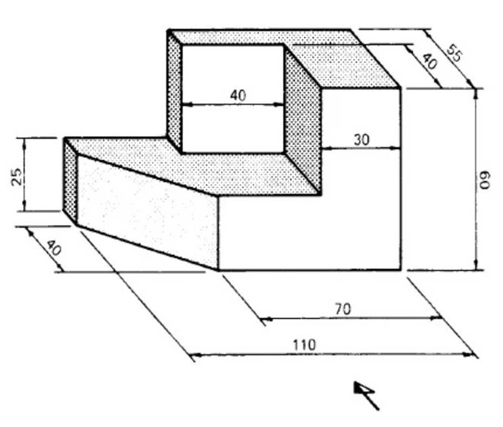
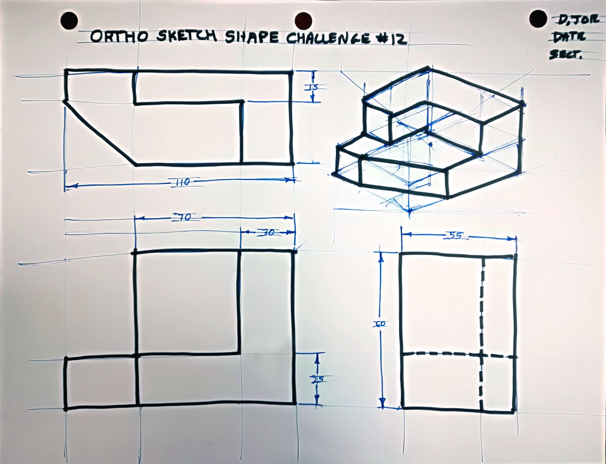
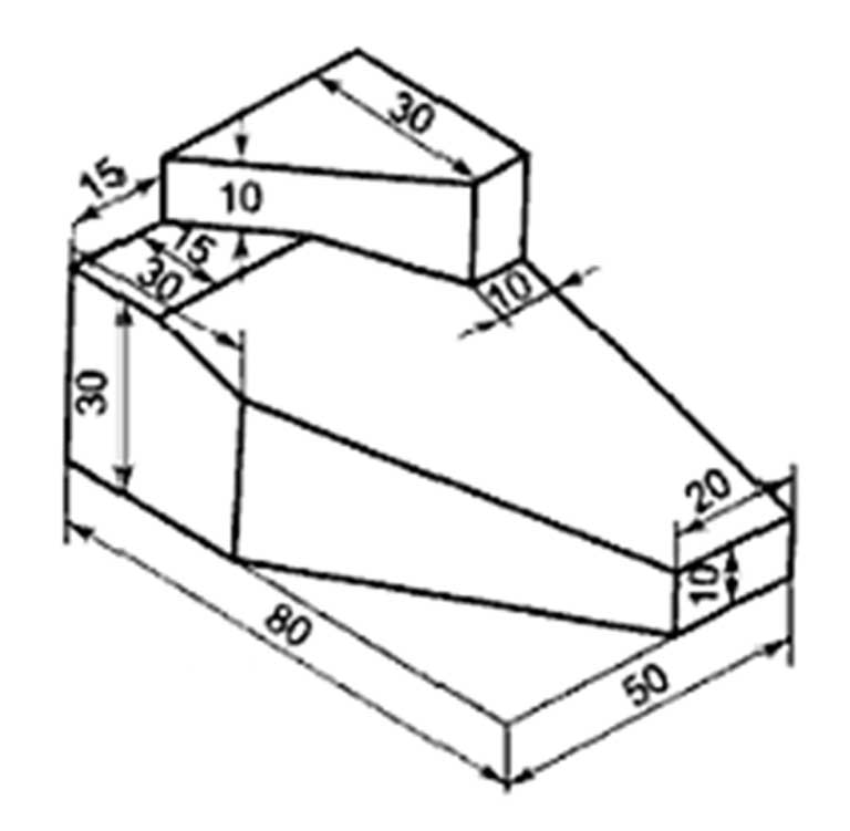
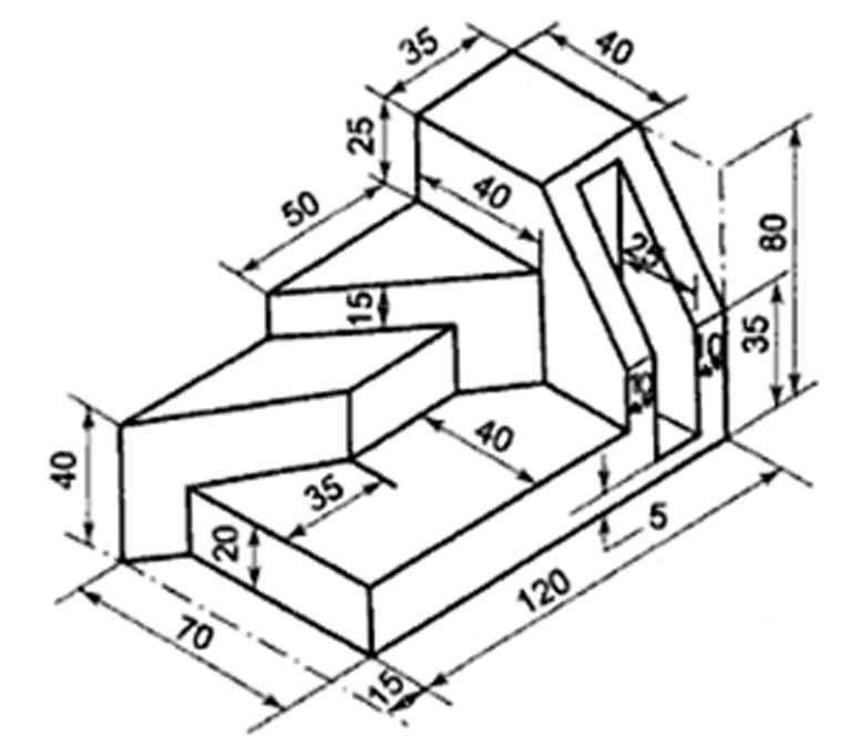
Orthographic Sketching Challenge
Use the ortho graphic note, discussion, demonstration, and Ideas/Investigation section of information and tips on technical sketching, engineering standards, dimensioning, and common mistakes made when sketching, to help you complete your ortho challenge. Check out the ortho sketch rubric for tips and hints to completing the Ortho Challenge with success.
Steps to Follow
- Select one of the orthographic sketching challenges below to apply/practice layout, line weights, techniques, process, and engineering standards
- Choose the front view based on the three rules for selecting the front view to start your sketching challenge
- Using two-stage sketching line-weights, layout and block in appropriate scaled (use the full page) 2D ortho views, usually the front, top, and right side with equal spacing between those views
- Ensure all object features are aligned in each of the views using construction lines
- Remember to apply the correct line type and thickness with the secondary sketching stage for each of the finished line types (dimension, extension, object, hidden, and centre lines)
- Show minimum necessary overall and detailed dimensions in the correct locations
- After dimensioning is done, then sketch the isometric in the top right quadrant with proper centreing and appropriate scaling
- Finish with the header - title, your name, and the date (6 and 3 mm guides in Gothic font style lettering)
- Fill in the Ortho Sketch Checklist and do a self and have a peer also evaluate, then fix and/or update if necessary
- Digitize both your final sketch and completed eval sheet as one PDF file, to submit in Google Classroom
![]() Remember to apply your sketching techniques previously learned. Review the "Sketching Tips" and "Common Mistakes When Sketching Orthographic Views of Objects" in the Investigation/Ideas section above.
Remember to apply your sketching techniques previously learned. Review the "Sketching Tips" and "Common Mistakes When Sketching Orthographic Views of Objects" in the Investigation/Ideas section above.
Ortho Sketch
Challenge 1

Ortho Sketch
Challenge 2
Ortho Sketch
Challenge 3
Ortho Sketch
Challenge 4
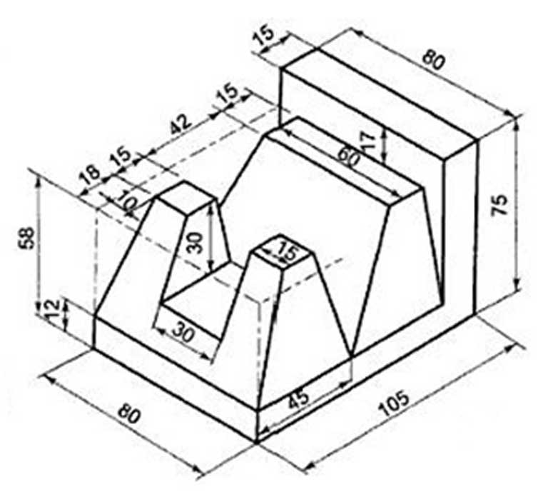
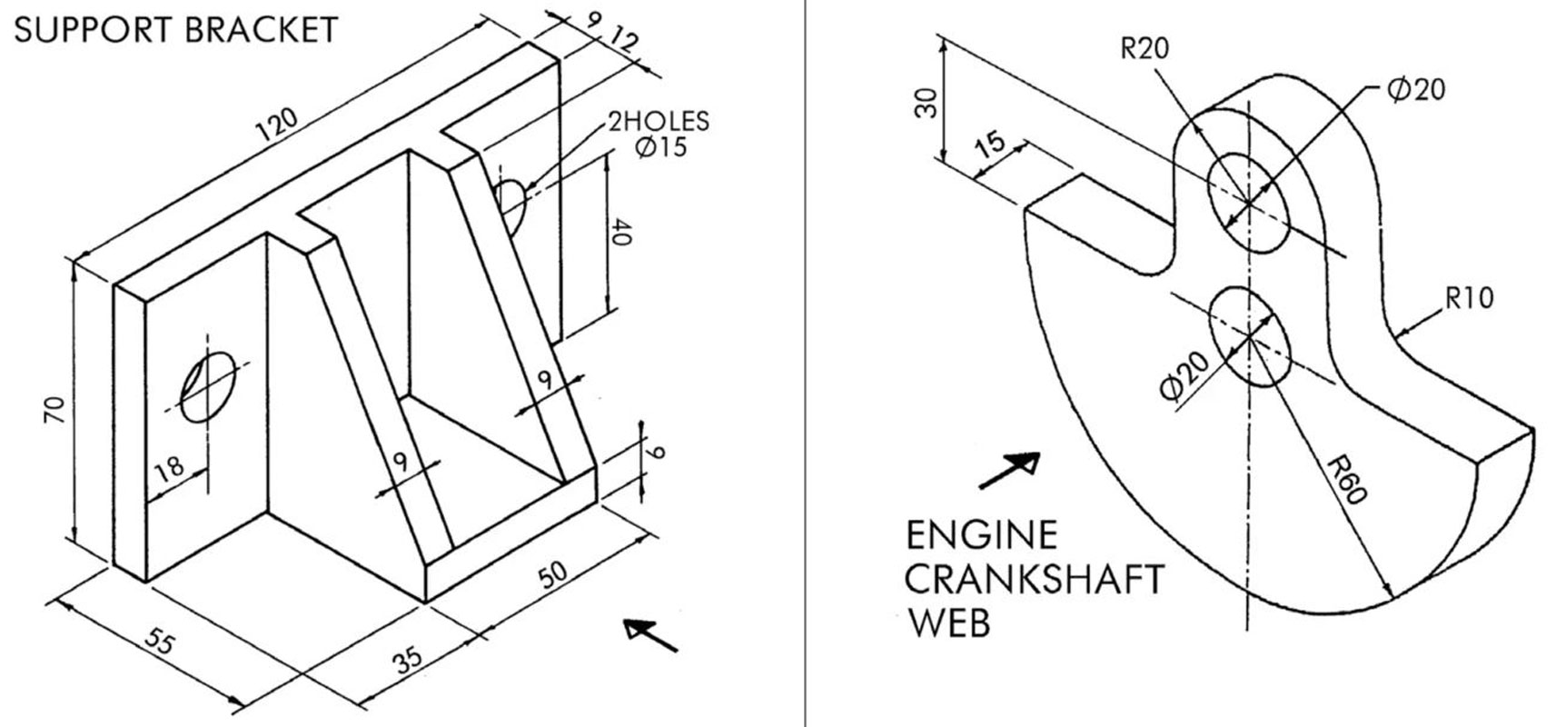
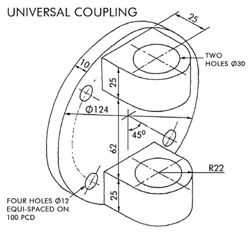
For Grade 12's, sketch one of these shapes in third angle projection with the exception of the Locating Guide & the Engine Crankshaft Web
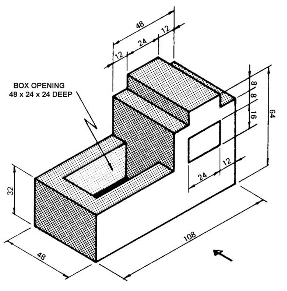
Adv 1
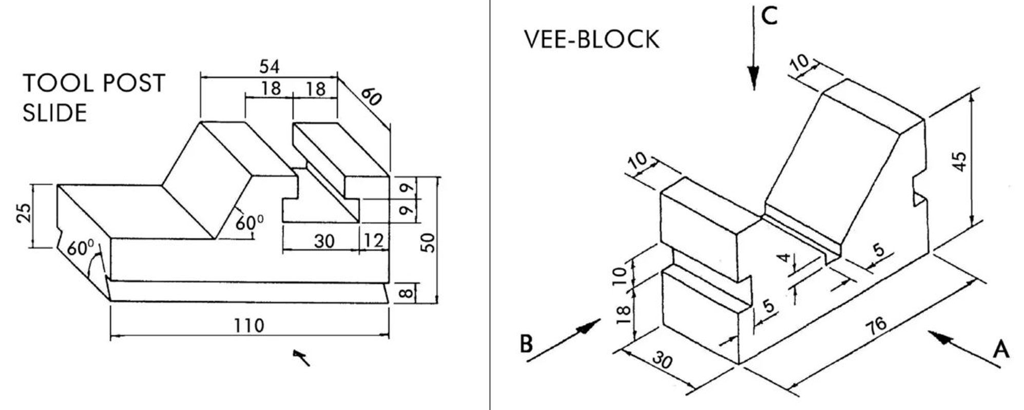
Adv 2&3
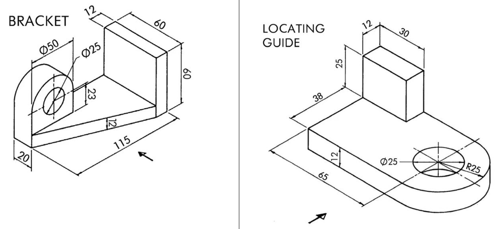
Adv 4&5
Adv 6&7
Adv 8
Evaluation:
You will be evaluated based on the completion of the above sketching assignments.

| Evaluation Breakdown Component Descriptions | Marks |
|---|---|
| Always double check that you have completed all components for full marks. | |
| Sketching Shapes - clear shapes sketched with correct angles, lines, and shapes | 20 |
| Sketching Shapes Challenge - Combined multi shapes with shading | 20 |
| Orthographic Sketch Challenge - 3 ortho views, 1 ISO, and dimensions | 40 |
Unit 2, Act. 2: Applying the Design Process

Situation:

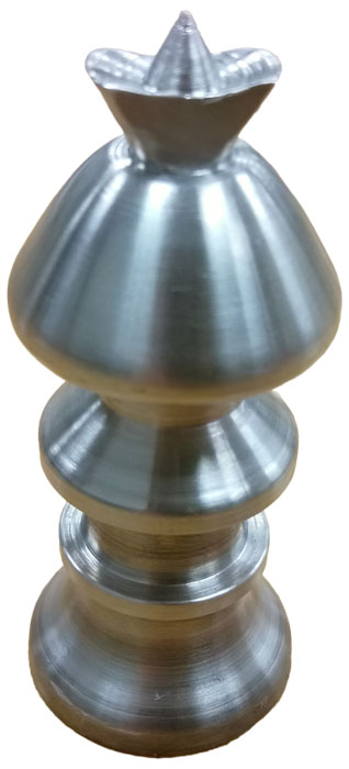
A class of students interested in the field of Engineering have taken a course to find out what Technology Design is all about. One of the major principals of this course/field is the "Design Process". Coming up with solutions using practical steps is what Engineers do on a daily bases. Manufacturing Students currently create chess sets as part of the grade 10 course making use of common manufacturing machines and looking for a refresh on theme and design with Technological Design students.
Problem/Challenge:

Students will do a class project collaboration between two classes - Manufacturing and Technological Design. Students will collaborate a new themed chess set design (approved by instructors) that will make use of the mill and lathe machine processes. Design must be simple, consistent, similar to current and relative sizing, and easily manufactured using common manufacturing machines in our machine shop.
Manufacturing will support Technological Design students with current manufacturing process capabilities and current chess set designs/specs. Technological Design students will design a new set based on new agreed theme.
Technological Design students will finish with final model designs and build drawings to pass on to Manufacturing students to manufacture. Prototypes will be also 3D printed as an alternative end build result in-class
Students will identify and report on the SPICE design process in relation to this project to show their understanding of the SPICE design process and how it relates to this project.
You will need to show the following when going through the process of this project:
- The steps of SPICE explained in terms of this project the chess piece
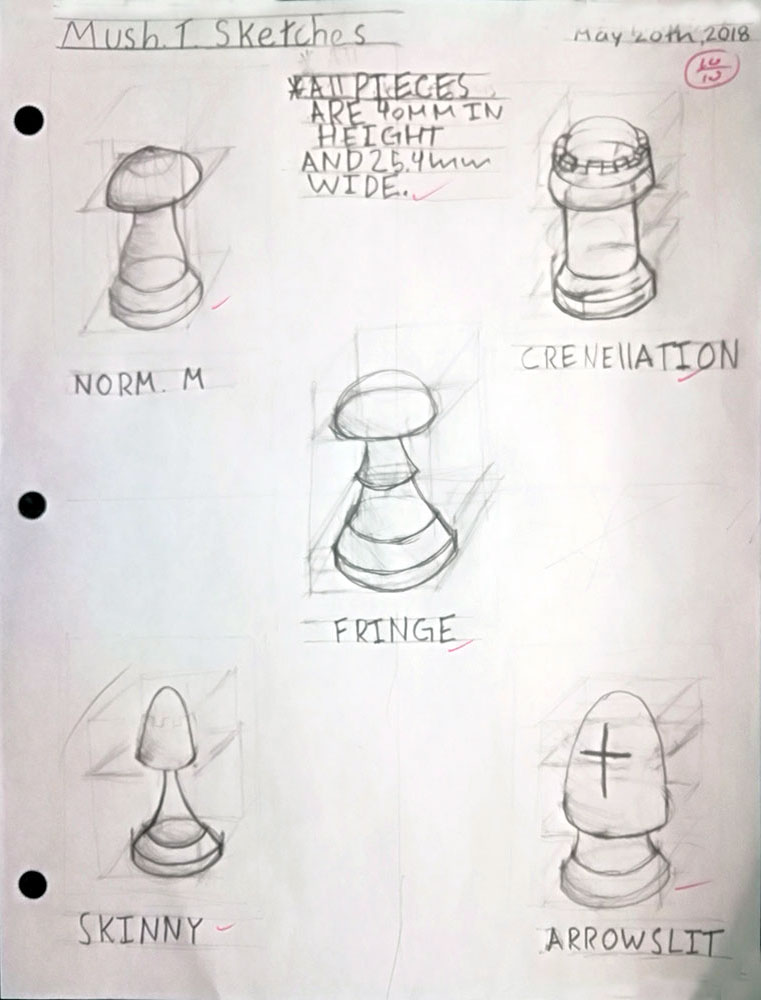
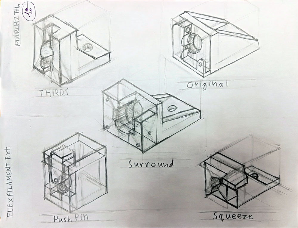
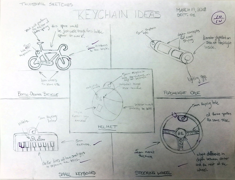
- Sketches showing layout of Five different thumbnail ideas with labels
- Final full page scaled orthographic freehand sketch including build dimensions and an isometric view
- OnShape model and build drawing
Details to Keep in Mind
To keep design consistent with current chess project designs, here are some things to keep in mind when designing your piece:

- Keep design theme practical
- All pieces maximum diameter- 25.4 mm, recommend all bases, 4 mm high at max.
- King maximum height - 75 mm
- Rook height - 37 mm
- Pawn height - 30 mm
- Keep design simple
- In DWG, curves in your design need to be identified with angles and distance, see Sample DWG 10 above

Seniors will customize their own idea, which will require a ![]() proposal - MS Word form to be filled out and approved by the instructo . The idea must still follow the same process of current project group, scope, size, and have cylindrical features with the intent to 3D print and later manufacture.
proposal - MS Word form to be filled out and approved by the instructo . The idea must still follow the same process of current project group, scope, size, and have cylindrical features with the intent to 3D print and later manufacture.
Investigation/Ideas:

Design Process
A design process is what engineers, designers, inventors, etc. use or go through to come up with great solutions to resolve or find solutions to problems. There are many design process models out there, some very long and detailed wile others simple and short. Most successful corporations will already have a process that employees must follow while working on company projects which always involves reporting on steps taken. We will look at some of these models and focus in on one specifically called SPICE to show how the technical design process works.
Resources
Below are some support links related to this project that may be helpful:
- SPICE Design Process Model (We will be using this model)
- A detailed look on each stage of designing
- Six Models of the Design Process
- Thumbnail sketching - some samples
- Thumbnail Sketching in a design process- a detailed look
- Freehand sketching to develop the idea and plan 3D modeling
- Wikipedia on chess sets
- Chess Set Guide
- 30 Unique Home Chess Sets
- Pinterest chess pieces designs, more ideas, and even more
- Thingiverse chess sets
- Cool chess sets
- ChessHouse and Amazon
Student Samples of Work
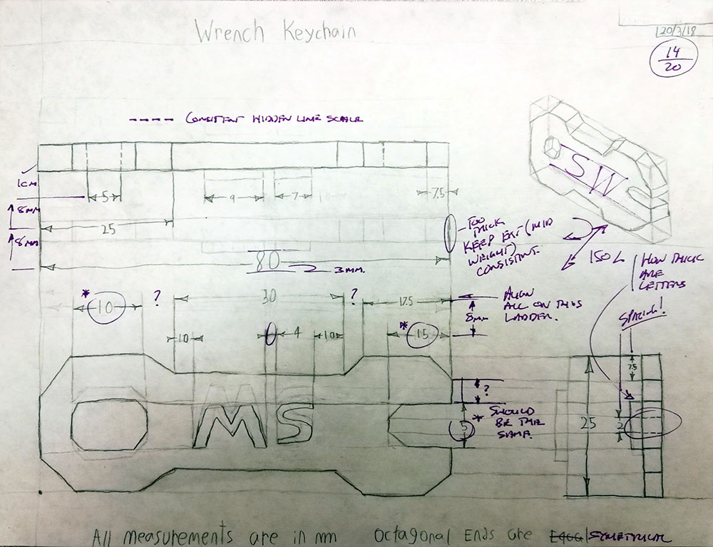
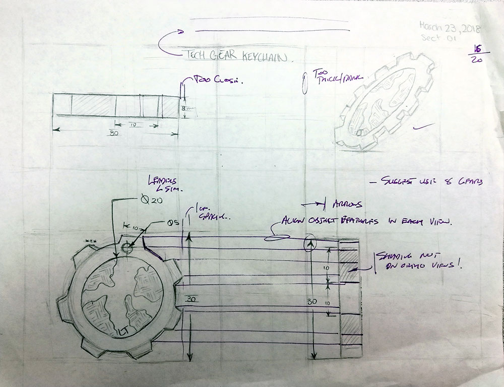
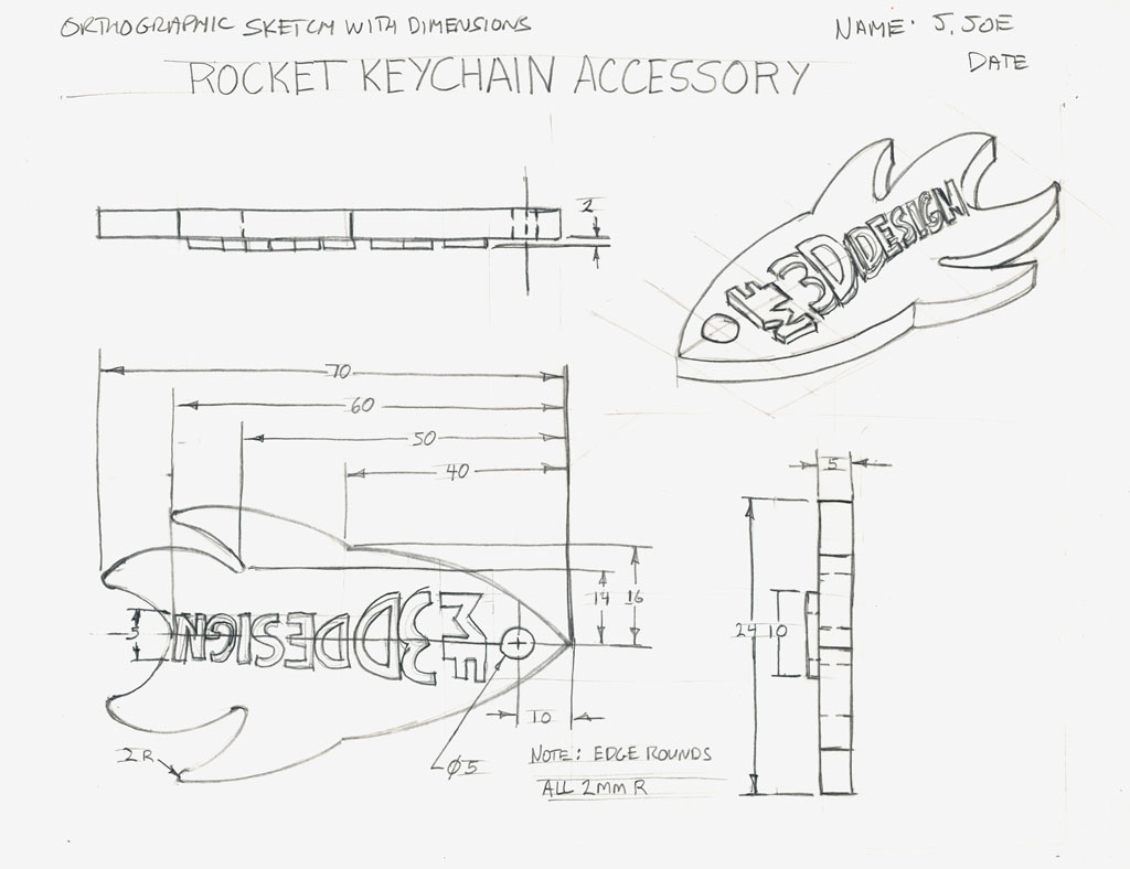
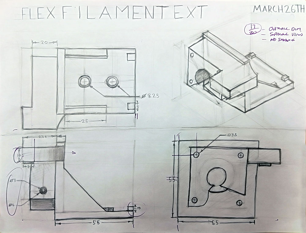
The following samples show what thumbnails and orthographic sketches would look like. Pay close attention to layout, sketching technique, use of page space, dimension placement, block view construction, line weights, etc. This is a great way to look at and discuss common mistakes and what could be improved on each of the student samples.
Sample 1
Sample 2
Sample 3
Sample 4
Sample 5
Sample 6
Sample 7

Sample 8
Sample 9

Sample 10
More student samples can also be found in the gallery.
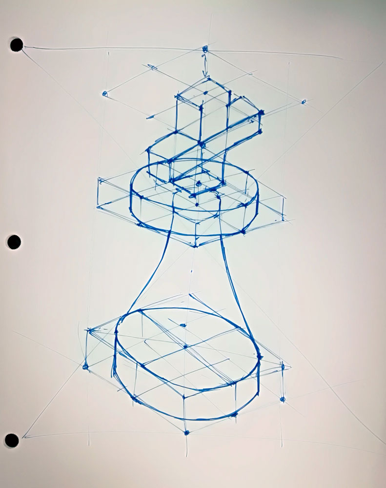
Cylindrical Isometric Creation
Below is an example of creating an isometric sketch by first centering in space, creating a baseline, ~30 degree angle lines to start a square base in this case, then creating a full height wire-frame rectangle, then subdividing it up for major design feature using parallel lines on ~30 degree and verticals. First two show full page rough practice and the last image showing the start to create 5 ideas by laying out the page.
Cyl ISO 1

Cyl ISO 2

Cyl ISO 3

Cyl ISO 4
Remember to start by centreing your ISO in the space you did in your layout (for header and maximize use of paper space and scale of your thumbnail ideas), then use ISO block construction to create your levels or parts of your cylindrical shaped object to "build" properly on paper what it should look like based off of your ~30 degree ISO angle lines from your base line and ensure all of them are parallel to each other.
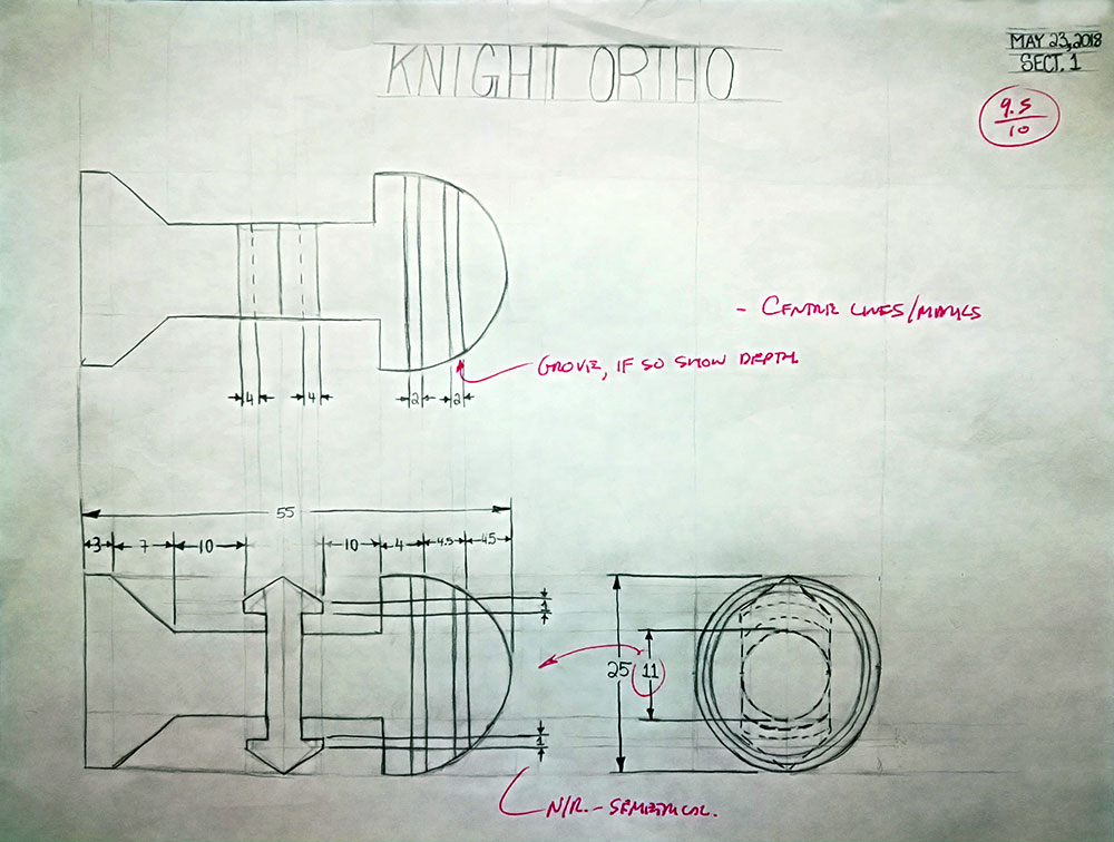
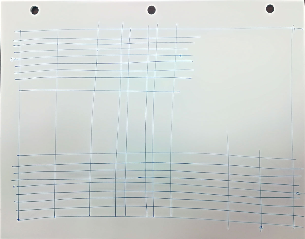
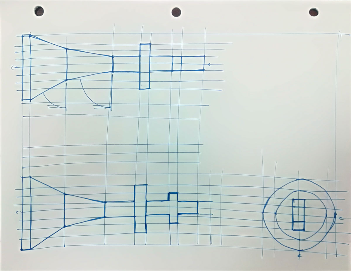
Cylindrical Ortho Creation
Below is an example of creating an ortho sketch (lots of extra detail here, from from Grade 10 course) by first laying out the page, getting a start point for front view. At this point you need to think about filling the page and ensure your scaling and spacing are reasonably close to what they should be and that you are filling/maximizing the space on your landscaped blank page. You should have a small quick sketch showing the views, with the correct front view drawn based on the three rules for selecting the front view . You may only need the Front and Right side view in some cases for cylindrical objects, as the third view may not be required, as the extra view will just repeat current view making it unnecessary.
Sketch light construction lines for all major features of your cylindrical object showing alignment in the other views, then using a medium weight, outline your object using those alignment lines already created, then sketch construction lines to locate your levels of dimensions ~10 mm out for the first level of dimensions and ~8 mm for further levels, layers, or ladders of dimensions and rough placements of them using ~3 mm guide lines.

Cyl Ortho 1
Cyl Ortho 2
Cyl Ortho 3
Cyl Ortho 4
Once you have your views located with your dimensioning, then you can start work on your isometric in the top right/third quadrant to fit, and best to lean on a 45 by adjusting your baseline. If your object has height, maximize to fit from bottom left to top right with the best possible view showing the most amount of detail.
While your intention is to keep your design simple, if it is somewhat complex, you may need to also consider inclulding Ordinate dimensioning style also, to communicate your dimensions effectively in a neat and organized manner. Review the following ![]() Dimensioning Styles that are possible, but keep in mind that standard linear should still be used/shown with overall and detail dimensions.
Dimensioning Styles that are possible, but keep in mind that standard linear should still be used/shown with overall and detail dimensions.
OnShape

OnShape is a cloud based parametric 3D CAD application that can be used through a browser. Operation and tools work similar to other CAD based applications. Because this is cloud based program, your files are saved on the cloud and can be accessed anytime through your OnShape account.
Before you can start using OnShape, you will need to register for a student account. Once you have registered update your profile by going into your profile settings and upload a face image, fill in your information and ensure that you use only your last initial, first name for your forum and nickname field areas.
You will need to be familiar with 3D modeling, OnShapes' interface, design intent, sketching basics,dimensioning, and constraints. Using OnShape will allow you to learn some new techniques with sketches, dimensioning, and constraints.
OnShape Resources
OnShape was introduced in previous grade level and has several resources your can check out, some of which have been put below:

- OnShape About Us, 2.11
-
 OnShape General
 - OnShape Help Documentation
- OnShape Videos Main Page
- Software Overview and User Interface Tour, 4.56
- Parametric Modeling and Feature-Based Modeling, 6.01
- Design Intent, 4.44
- Sketching Basics, 3.56
- Dimensions and Constraints, 4.25
- Extrude Feature Tool, 3.25
- Revolve Feature Tool, 1.56
- Fillet and Chamfer Feature Tools, 2.59
- Sweep Feature Tool, 2.27
- Draft and Shell Feature Tools, 2.38
- Direct Editing Feature Tools, 3.55
- Constraints Use/Projection Tool
- Make a Part - Drawing, 2.53
- Drawing Essentials, 5.04
- OnShape DWG Dimensions
- Onshape Shortcuts Chart
- Sample OnShape Chess Pice
- Replicating Objects
- Thingiverse.com - Chess
If you wish to go further on your own, at your own pace, OnShape has a Training Dashboard you can use to work on different tutorials to further your learning with OnShape. Just log-on to OnShape and go to your OnShape Training Dashboard to get started.
Browser
 You need to use Google Chrome (or Firefox Mozilla) to work with the OnShape CAD engine on the PC, so ensure that you set your default browser so that when you click on a web link from your computer that it goes to Google Chrome and not Explorer. If not set, you will need to copy the link manually into memory, and paste into Google Chrome browser. You may need to test and/or adjust some settings on your recommended browser.

Tips
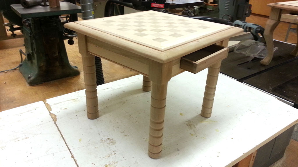
Chess Table
Remember to save the file with the proper CAD file naming convention: course code/section, your last initial, first name, project name, file type, description format. Example: td3-1_d-joe_chess_P_king-75x25.4mm.SLDP
Make sure you have all your sketches Fully Defined prior to extruding, by making sure no blue lines are showing in your sketch (should be all black). Red represents over defined which means there are too many constraints or dimensions and you will have to remove some. Use dimensioning techniques and make 2D sketch dimensions organized and fully defined. If you find that your part is not filling up with a light grey once you have closed all shapes, then you will need to check your line connections. Also ensure that your version FV1 of your part is showing the best isometric view, fitting on screen.
Once you are finished a design model/DWG, you will need to create a final version "FV1" using the manage version button, use the description area to add supporting notes, then save version, and share it with your instructor (use e-mail address from the bottom of this page) so your instructor can view with full edit access for evaluation.
3D Printing
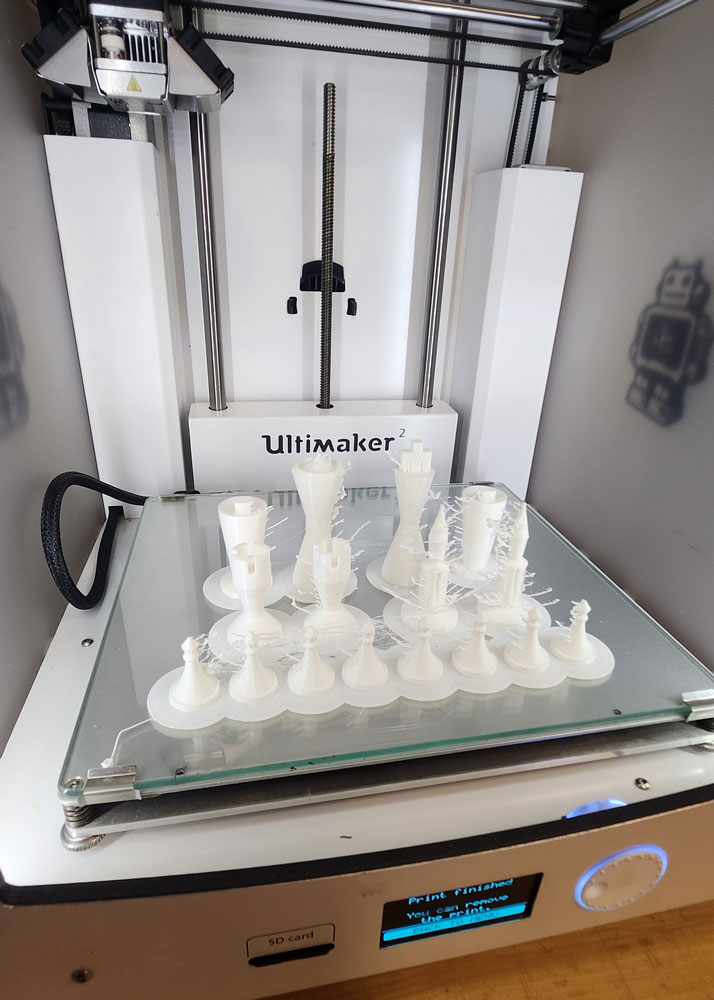
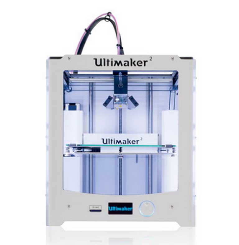
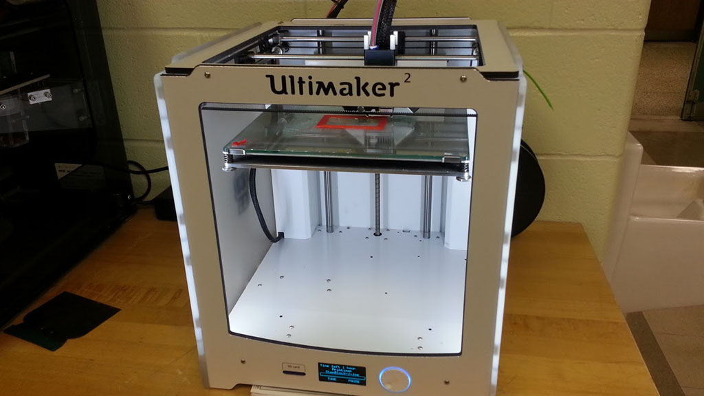
Printing in 3D is relatively new, last 10 years, and is now more common today to find a lot of hobbyist to have these in their home. The market is still expanding and new technologies, methods, and types of printers and print material is in constant flux. For this reason you can see a wide range of types and sizes out there. Ultimaker 2 is one printer that has been rated one of the best on the market for it size and use in a consumer environment.

3D Related Resources
- What is 3D printing?
- Beginners Guide
- ULTIMAKER 2
- Ultimaker 2 3D Printer review
- Ultimaker2 User Manual
- CURA 15.04
- Learning Exchange Tutorials
- Cad Digest Tutorials
- 3D Printing Industry News
- History of 3D Printing
- What Is 3D Printing?, (2.21)
- GIANT 3D Printers!, (3.46)
- 7 Shocking 3D Printed Things, (7.11)
- Cleaning nozzle, 1.34
Just like you learned how to sketch the step block either by additive or subtractive methods, you can see the similarities with 3D printing vs machining. Looking at the process of 3D printing, you can observe that this is a "additive technology" meaning when making/creating a part it adds material to build the part. The opposite is true with to today's machining process, which creates parts by taking material away and can be looked at as a "subtractive technology".
3D Printing Process
With the Ultimaker 2 3D printer, you will be able to print your design in 3D. It does this by melting plastic it draws from a roll through a plastic tube into a heating chamber that melts the plastic and the head is controlled by an x/y axis bars and servo motors which the printers controller runs based on the G-CODE of that object . Each layer is controlled by the Z axis, A little history and general information can be found here. Settings and maintenance can be found in the ![]() Ultimaker2 User Manual.
Ultimaker2 User Manual.
You will need save a copy of your part file (instructor checked design) as an STL file in SolidWorks. Using conversion software from Cura you will be able to build a AMF and GCODE print file from your exported standard STL file. It is important to place your digital object on the pad in Cura for best possible print. Both files are saved onto the SD flash card and then inserted into the Ultimaker 2 SD slot, The Ultimaker 2 glass base should be cleaned with a wet paper towel or similar, dry wiped clean, and then rub printing area with a glue stick to insure the plastic sticks to the glass base when printing. Here are some of the basic specs:
Price: ` $2500
Dimensions: 14.1 x 13.5 x 15.3 inches
Build volume: 9.1 x 8.9 x 8.1 inches
Filament: 2.85mm
Print speed: 30mm - 300mm/second
Software package: Cura
File types: STL/OBJ/DAE/AMF
Supports: Windows, Ubuntu Linux, Mac OS X
Connects with: USB, WiFi, SD card
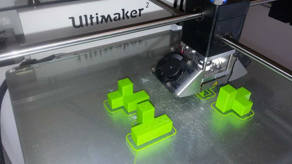
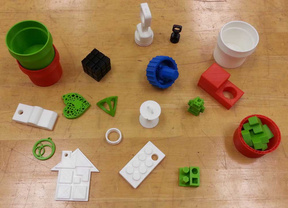
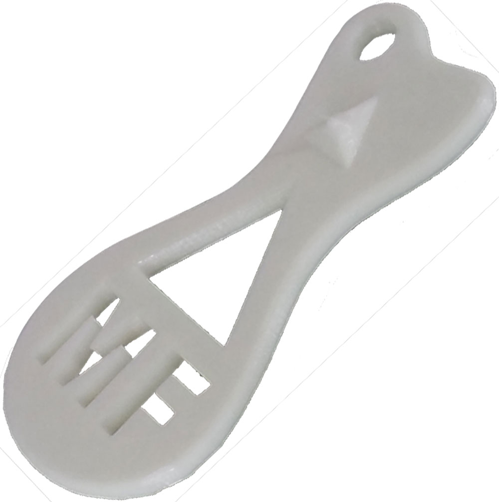
Sample Pictures
Below are some pictures of our Ultimaker 2 printing in action with some recent prints.
Sample 1
Sample 2
Sample 3
Sample 4

Sample 5
Interesting 3D Printer Facts:

- Can be used with any CAD program that has the ability to export .STL files
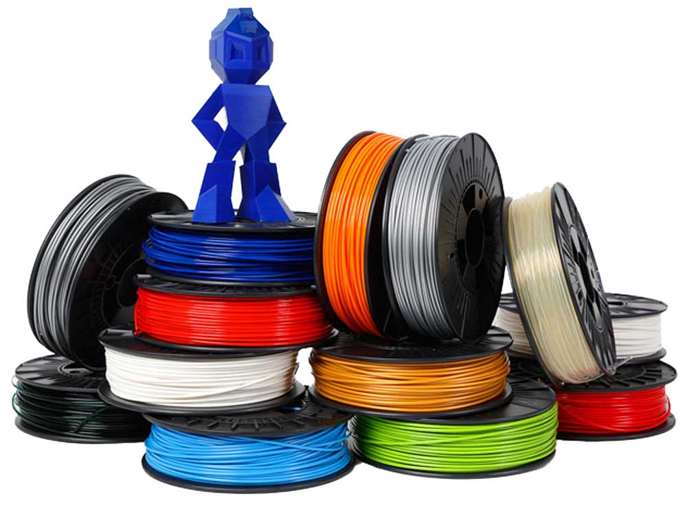
- Supports several thermoplastic materials with two of the most common: PLA and ABS
- PLA is the easiest material to work with and is considered a biodegradable thermoplastic that has been made from renewable resources such as corn starch and sugar cane. It is a preferred choice for support material, but will go brittle when exposed to sun and air in a short time, and is for this reason we will not normally be using it.
- ABS is the second easiest material to work with and is an engineering polymer commonly used to produce car bumpers due to its toughness and strength. It does however have a tendency to warp on larger geometries but is very stable in not going brittle like PLA
- Support material is used to make scaffolding in low resolution to support the geometry of a model which otherwise would be printed in mid-air, can be removed by simply breaking it away/off of your printed part and then sanding or filing to finish off.
- Finish surface quality depends on the geometry and layer thickness you are printing. For example the 0.125mm layer thickness will result in a smoother surface compared with the 0.25mm layer thickness, however it will take longer to print.
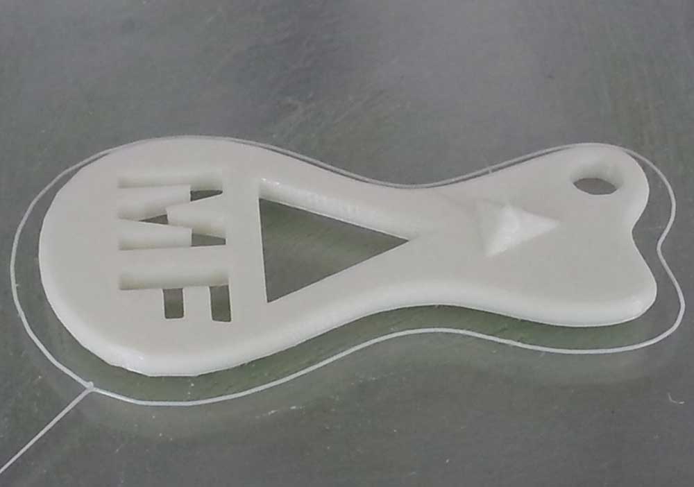
3D Model to 3D Print Process
You will need your STL file from your key ring accessory prior to creating the G-CODE file using Cura. Use the following steps to print your 3D key ring accessory:
- Printer upgrades Ignore: Nothing to upgrade, just bypass this by selecting Finish
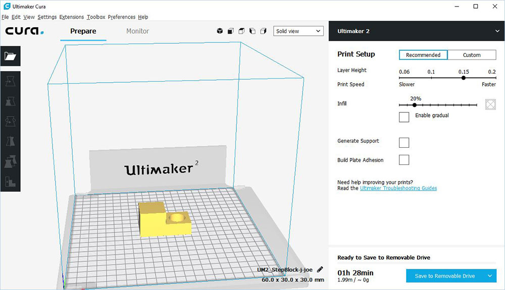
- Select Ultimaker 2: Start the Cura application. If this is the first time running it you will see a configuration wizard window. Select Ultimaker 2 for the printer unit and click Next
- Application layout:Click on File menu, and select Load Model File, and use the window to select and load your STL model part. At this stage you may need to rotate clicking the rotate tool icon in the lower left corner, which will activate the X, Y, and Z rotate circles. Just drag your object to rotate to a better print setting, for example the step block hole is better printed with the centre perpendicular to the platform
- Settings: Set layer height to 0.15 with infill at 20% with no support and build plate adhesion (normally) unchecked. Certain situations will require one or both on.
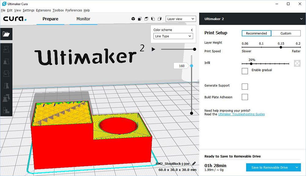
- Layer Build View: This shows an example of halfway through the print and if you look closely you will see the web framed internal design
- Save G-Code: Saving the G-CODE is what the Ultimaker 2 will use to print your object, name file using our file naming convention, ex: td2-1_d-joe_2d-step-block_60x30x30mmand.GCODE, then save. Note if you make changes to your STL file while in Cura, you should also save those changes, or the next time you print, you will have to redo the set-up
- SD Card adapter: You need the adapter and the SD card from Ultimaker to transfer the files (g-code and STL) on to SD card, then put back into Ultimaker SD slot
- Control Panel: Rotary dial is used to select Print, then you rotate to find your G-CODE file which will show the print time and amount of filament plastic will be used, press the rotary button to start print. Heated glass platform should be cleaned using a little bit of water and paper towel if needed
- If your print is challenging, you may need to put some glue down from glue stick to ensure print sticks to the platform
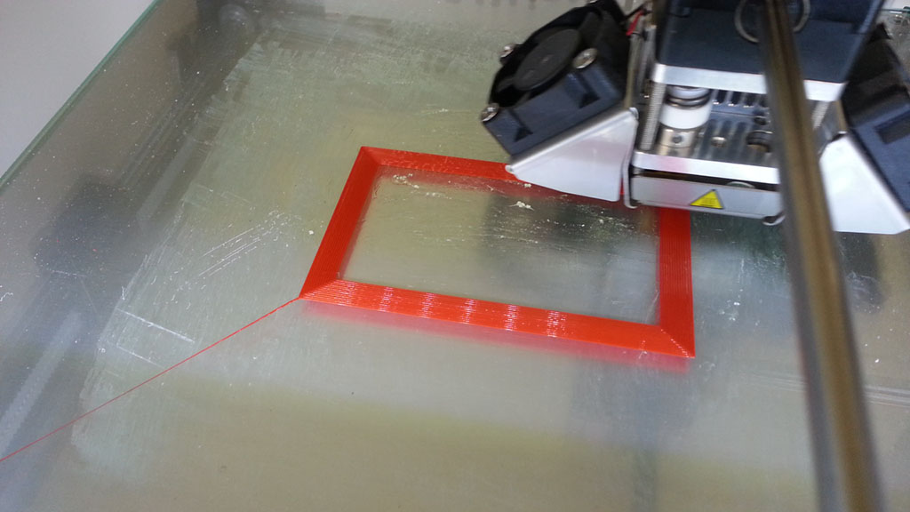
- After starting the print, the print head heats up for about a minute, then will start printing
- You need to watch and make sure first layer prints correctly, if not, you will need to abort print and try again after checking filament feed
- Half way through you can see the glue on the glass and the small print head with a servo motor to the left which drives the track/rails
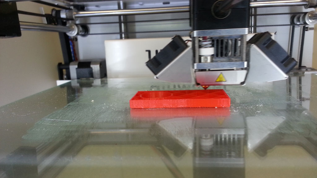
- Part way though the print you can see the web frame structure inside the object print, i.e. objects are not printed with solid plastic as this would take a lot longer and use more material
- Print Finished: You will need to use a thin scrapper to work object off of glass platform once it has had a chance to cool down
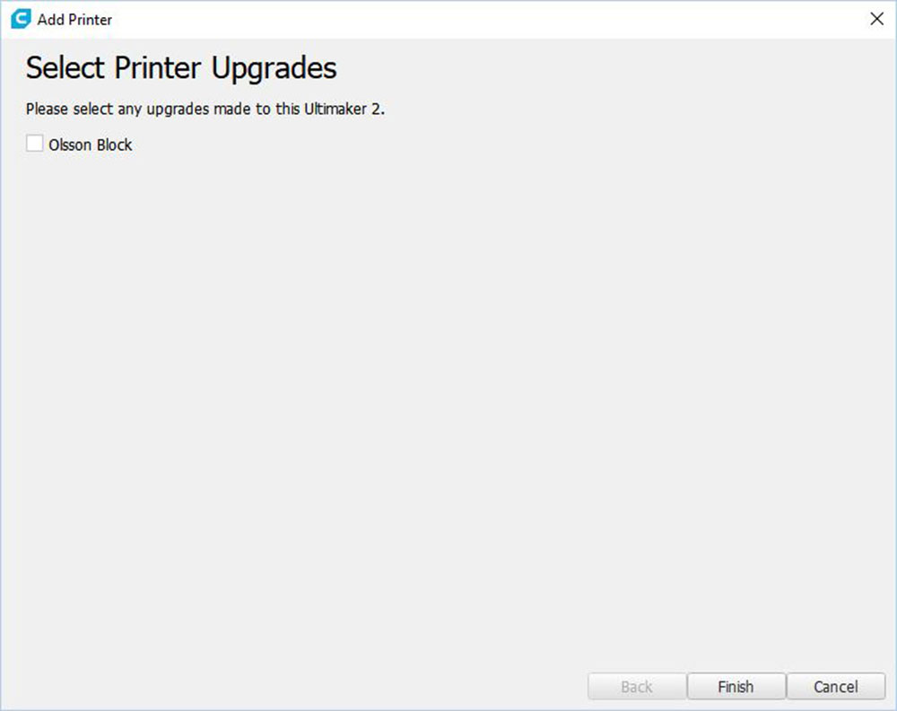
No upgrades
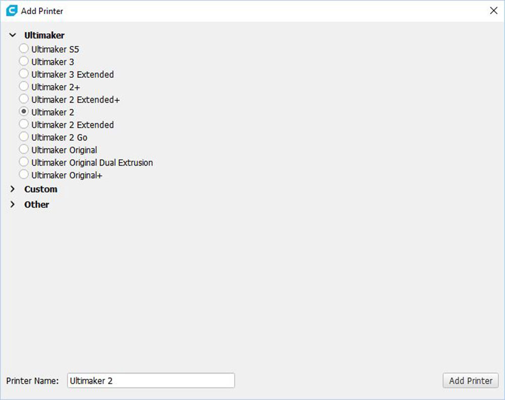
Add printer

Ultimaker 2
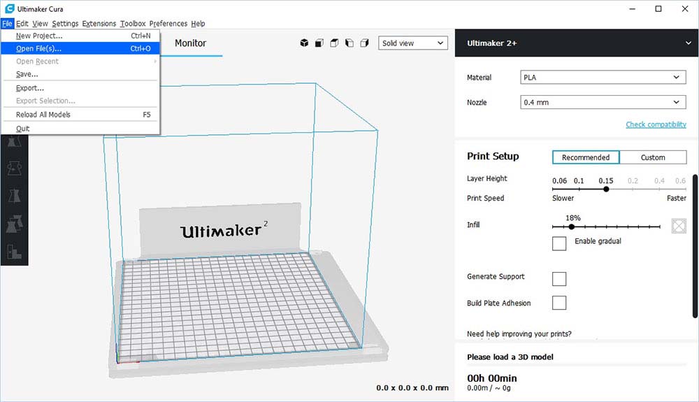
Application

Open STL
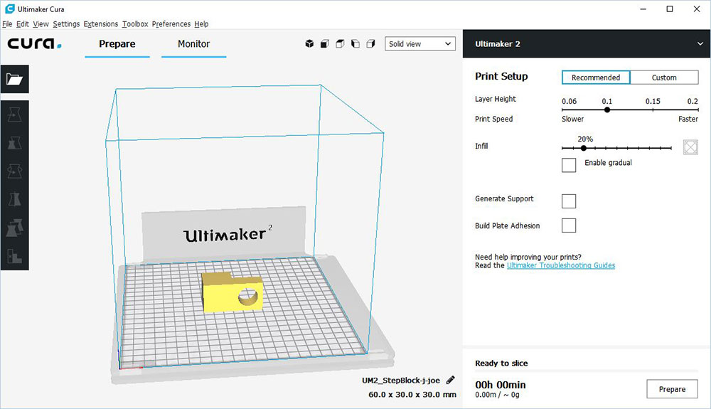
STL Opened

Rotate tool
Placement
Preview

Control Panel

Printing Started
First Layer
Half Way
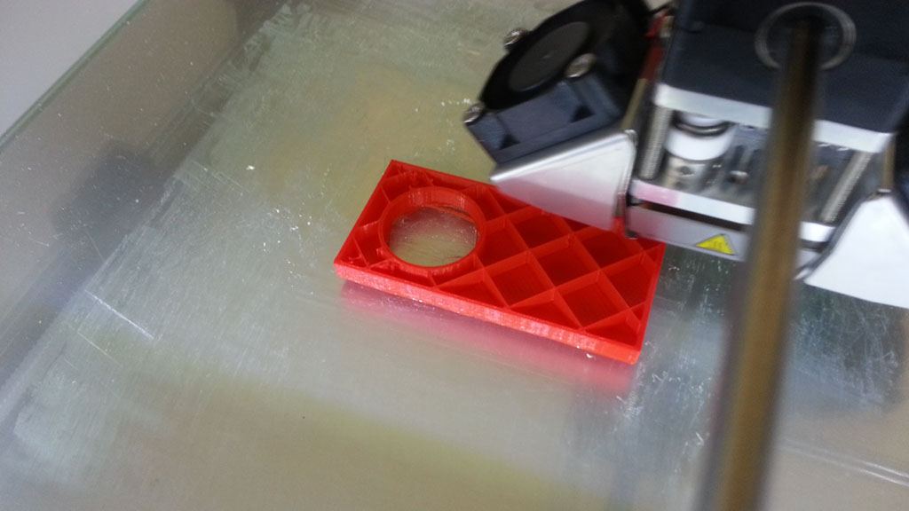
Inside support
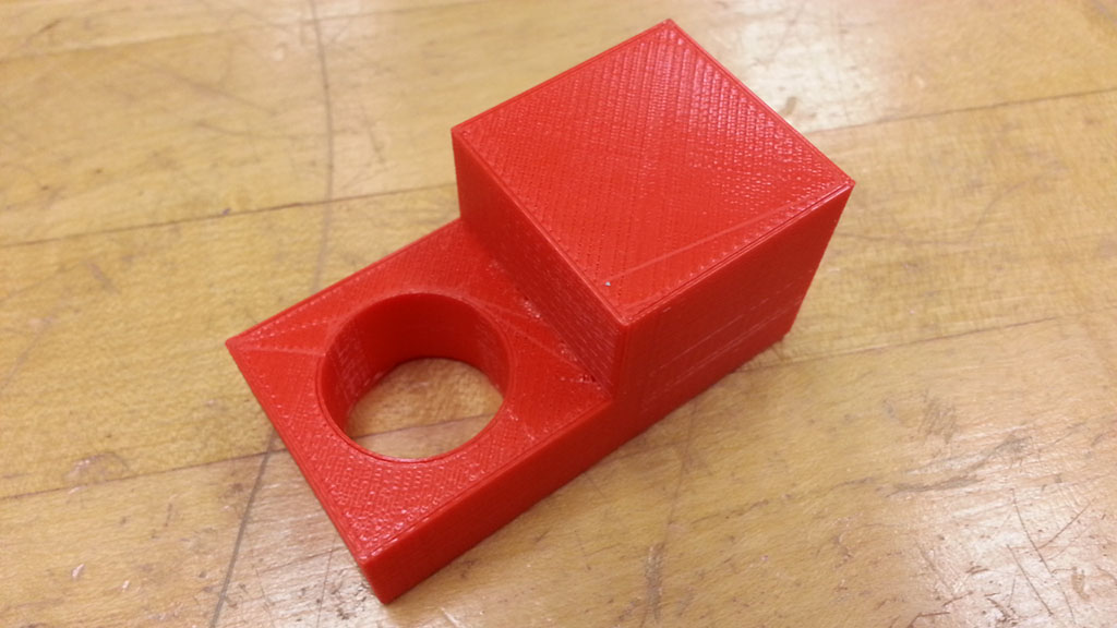
Print Finished
Remember to take some pictures of the 3D printing process to use in your design wiki page.
Create/Construct:

On Track

Keep yourself on track with project components. All of the work can be done in-class or from home. Nice thing with OnShape, it can also be used from anywhere and on many different devices as it is browser based vs application based. Total time for this project is two weeks. Here is the breakdown:
- 2 days - SPICE applied
- 2 days - 5 thumbnails sketched
- 2 days - Ortho sketch with dimensions and ISO
- 2 days - OnShape Link Bracket model tutorial and drawing
- 2 days OnShape Chess piece model and drawing build set
Chess Design Steps
A one page handout with details has been made for students to use with this project. The first step is to look at the SPICE design model and then identify the steps for this project using ![]() SPICE Applied - MS Word form. Looking at several designs already made will help with your creative themed ideas.
SPICE Applied - MS Word form. Looking at several designs already made will help with your creative themed ideas.
Major steps for this collaboration between Technological Design and Manufacturing classes:
Collaboration
Machine Shop

Tech Des. Lab
- Meet for initial exchange of manufacturing process capabilities, current design, and decide on theme for new design in 6 groups one for each chess piece.
- Technical Design students to come up with 5 sketched thumbnail ideas for each chess piece, for group vote on final design
- Technical Design students to create orthographic sketch of final design with dimensions for group refinement and finalization
- Technical Design students to create CAD model and manufacturing drawings for manufacture (3D print and machine creation)
- Manufacturing students to manufacture chess pieces to be later checked by Technology students for quality and accuracy

OnShape 2D Sketch, 3D Model, and Ortho/ISO Drawing Tutorial
To get familiar with the program a simple Link Bracket tutorial will get you familiar with OnShape. Check out how your OnShape account should be set-up by reviewing the registration steps above, if you don't have an account set-up. You may review intro tutorials from grade 10 section to familiarize yourself with OnShape.
- Basic Sketching - Link Bracket (11's) along with the following instruction guide below (12's will work on the Gripper Arm):
- Rename with proper file name convention, ex: td3-1_d-joe_ link-bracket_P_L-shape-4.5x1.75x0.12in
- Select and draw the correct front view (hint - not the one shown) and keep in mind that your 2D sketch dimensions are required to be organized and fully defined
- Change your tab title to the actual part name "Link Bracket",
- Rename your feature extrude and part name in the feature tree area "Link Bracket"
- Create a standard 3 view ortho with dimensions and ISO using tdj201_mr-f_OS_ANSI_templates file with template mf-ANSI_A_INCH.dwt set-up for maximize space, then add a drawing using the "+" Insert New Element near bottom tabs, and add drawing using the template you just copied
- Name bottom drawing tab: Link Bracket (note you will have to delete some random empty text fields around the info block area as a result of template update)
- Drawing info block: Material: PLA, Finish: Normal, Weight: (find by selecting your part in your model view, click on small scale lower left corner, copy the weight and use note tool in the drawing tab to insert into info block), Title (input in model properties under Title one), Part & revision Number (input in dwg properties), Checker and date, etc. (use note tool) 6 mm (0.2362 inches) for title, 3 mm (0.1181 inches) to finish off info block
- Save your version titled FV1, put in the description section: the volume of the part, and five key things you learned in this project (bullets) using correct related terminology
- In the main menu, under Document Properties, put a quick one sentence overview of this project.
- Fill in the OnShape Model/DWG Checklist sheet - self and peer (peers to mark only once, so everyone has a chance to peer mark) and hand in the same time you share "Can Edit" with instructors email address (found bottom of all web pages here) for evaluation and feedback.

OnShape Drawing
Custom/Chess Piece Process
Use the feedback from the tutorial Link Bracket project to improve your knowledge and skills to use the same process to create your chess or custom cylindrical design. Your drawing should take into account the additive manufacturing process with regards to an overlay of cut angles and possibly Ordinat dimensions starting from the top of your project down to the base.
Handing in Work
Final ortho sketch to be self and peer evaluated using Ortho Sketch Checklist PDF and combine with your ortho sketch scanned PDF, for one file submissio. CAD Model and drawing to also be self and peer evaluated using OnShape Model/DWG Checklist PDF, to be handed with your OnShape CAD share link with full edit access, correctly named, ex: td3-1_d-joe_chess-piece_P_king-75x25.4mm.
Printing Design
Once you have your final chess or custom piece done, submitted, marked and design is approved for printing, it is time to 3D print it using our in-house 3D Ultimaker printer. Keep in mind, it will take time to print, usually an about an hour and you should be reviewing the support information and process in the Ideas/Investigation section, to prepare your design for print and MUST partner-up with a recent person that has printed to safely print your design.
Evaluation:
You will be evaluated based on your SPICE explanation, 5 sketched thumbnails, orthographic design sketch, and final CAD model/DWG files. Remember to include your self/peer evaluation checklist sheets for full marks.

| Evaluation Breakdown Component Descriptions | Marks |
|---|---|
| Always double check that you have completed all components for full marks. | |
| SPICE - report on the design process of product design and build | 20 |
| 5 Thumbnails sketches- full page layout, technique, labels, chess piece ideas | 15 |
| Orthographic sketch - layout, views, technique, dimensions, and isometric | 30 |
| Link Bracket CAD Model/DWG - Views, spacing, dimensions, and isometric | 25 |
| Chess CAD Model/DWG - Views, spacing, dimensions, and isometric | 30 |
| 3D Print - Completed 3D printed successfully | 10 |
Emergency Supply Teacher Instructions
In case of emergency, students can download the Matching Isometric with Ortho-Graphic View 2 challenge and complete using Adobe Acrobat Reader DC commenting tools (already installed on computers) for 12 marks. Next, they can work on Surface Identification Coupling Challenge again using the Adobe Acrobat DC commenting tools to fill in the answers for 30 marks. Students will be asked next day to submit after take-up and review in class.

Unit Conclusion
Being able to quickly sketch your ideas using technical sketching techniques with engineer standards will allow for easy quick communication of your ideas. With your practice of applying the SPICE design process to different challenges will allow you to use this process with just about anything that you need to find a solution to. Knowing and practicing these skills, steps, and knowledge will empower your confidence in the future to communicate and understand/apply the design process!