Unit 4: Grade 11/12 Technological Design - Robotics - Driven Mechanisms
This unit will continue with robot sample design build and then your custom robot based on FIRST FRC robotics with a focus on mechanisms - gears, gearbox to wheel, drive train, and a robot function using SolidWorks.
Course Units and Descriptions
Use this table for an overview and navigate to each of the course unit pages.
| Unit | Description |
|---|---|
| Review course outline for more details | |
| 1 | Careers & Safety- Intro, computers, organization, and research career |
| 2 | Engineering Communication- Technical sketching, ortho-ISO, custom ortho, and robot design |
| 3 | Structure and Materials- Materials & measurement, joints, frame, and 3D model |
| 4 | Driven Mechanisms- Gears, gearbox to wheel, drive train, and 1st function |
| 5 | Functions and Integration- Body base, pneumatics, 2nd and 3rd function |
| 6 | Robot Assembly- Robot build, function supports, drawings and presenting |
| 7 | Marketing and Portfolio- Web authoring, portfolio and presentation |

Unit Content Activity Quick Links, Click to Jump to Specific Activity!
- Unit 4, Act. 1: Drive System Assembly
- Design Build, STEP to 2D Profile, Import Resources, Profile from Scratch, 2D Profile to Structural,
(Create) Robot Drive System Steps, Evaluation - Unit 4, Act. 2: Tote Elevator Lift
- Design Ideas, Components, Roller Chain, Resource Links,
(Create) Basic Build Steps, Assembly Steps,Advanced Steps, Evaluation - Unit 4, Act. 3: Elevator Middle, Upper Frame Support and Gripper Tower
 Unit 4, Act. 1: Drive System Assembly
Situation:
With the frame of the sample and custom robot completed, the drive system can now be added. This process may involve making some more model parts and/or downloading and importing pre-made components, to start to build your drive system virtually in SolidWorks.

Problem/Challenge:
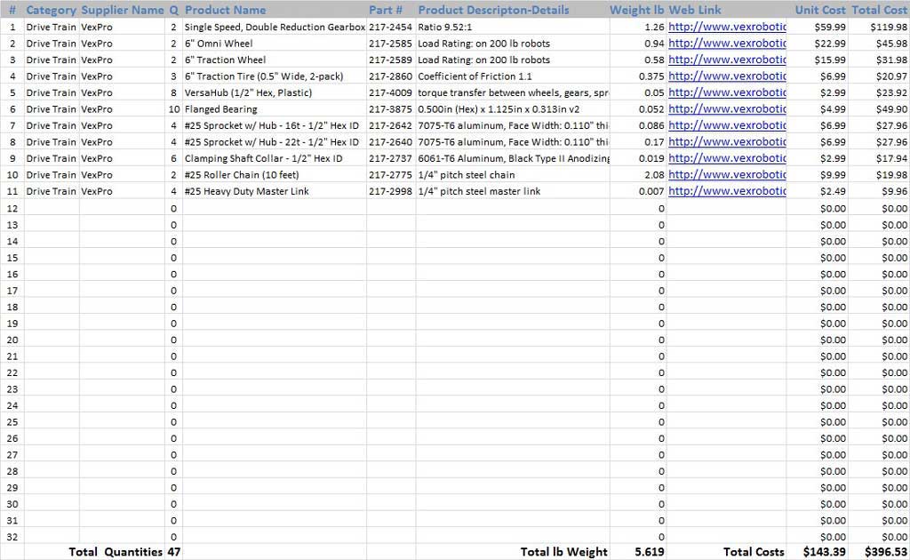
Create or download components needed for sample robot drive system, then create an assembly with the frame and drive system model components (sub-assemblies and parts). Using pre-made components, import them recognized or not into usable components in SolidWorks. Using the mating process, align and lock components to their correct locations to build your sample robot drive system. Folder organization for imported assemblies to be used for each wheel assembly, and sub-assemblies to be used for each front and rear drive systems. The main components you will be using can be found in your PMT pkg under the Material Cost Breakdown tab, an example table of what engineers use to keep track of detailed information on each of the components such as product name, descriptions, suppliers, part numbers,weight, web link, costs, etc. to later also include in drawings. Some of this list of components includes:
- Single Speed, Double Reduction Gearbox
- 6" Omni Wheel
- 6" Traction Wheel 1.5" wide
- VersaHub (1/2" Hex, Plastic)
- Flanged Bearing
- #25 Sprocket w/ Hub
- Clamping Shaft Collar - 1/2" Hex ID
- 1/2" ThunderHex Stock
- 1/2" Acetal Spacer - 1/2" Hex
You will also create a set of drawing sheets (8) in a drawing file to include:
- Drive system master assembly ortho/ISO, (overall DIM only)
- Exploded drive master assembly system - balloons, and BOM,
- Frame weldment ortho/ISO with 1 section and 3 detail views
- Gearbox assembly ortho/ISO, (overall DIM only)
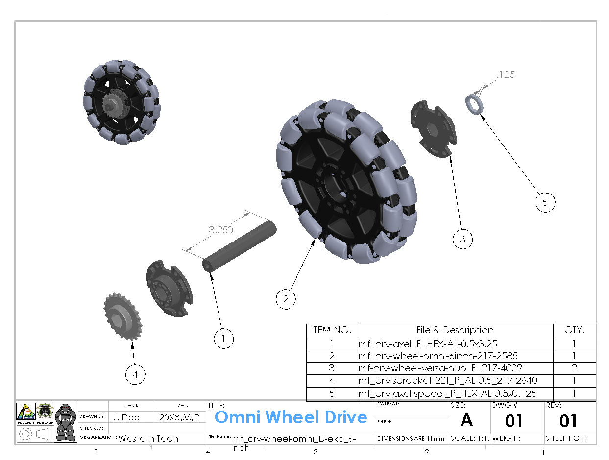
- Omni assembly exploded - wheel, shaft, sprockets, hub, spacers with balloon and BOM,
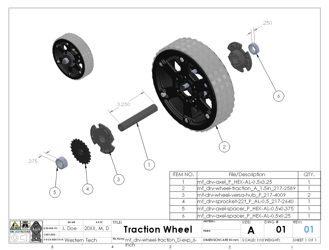
- Traction assembly exploded - wheel, shaft, sprockets, hub, spacers with balloon and BOM
- Hex axle shaft weldment ortho/ISO (typical)
- Hex axle spacer weldment ortho/ISO (typical)
Investigation/Ideas:

Design Build Options - Custom, Weldments, and Pre-made
To design and build your drive system, you will most likely need bushings or bearings to house the axles that will hold the wheels, drive transfer method components such as sprockets, and gear box. Axle could be sketched out, or in our case with the sample using the Thunder Hex shaft CAD part file, it can be downloaded and made into a weldment profile to use wherever it is needed. Anything with a pattern that is used multiple times at different lengths, a weldment should be used. Other parts such as wheels, gear boxes, sprockets, spacers, etc can be downloaded with STEP file, imported, and used to create the assembly of your build for the sample robot and/or your custom robot.
Recognizing imported STEP file is not necessary if you do not need to edit the part, thereby saving file space and complexity of your assembly. In some cases, recognizing errors may happen and you will have to use the imported step file as a solid unrecognized part (i.e. no editing of that part or assembly will be possible), unless you absolutely must have editing ability, then that component will have to made from scratch.

Related Resource links
- Pro Mgmt Pkg (PMT)
- File naming conventions
 How to change a sketch plane?
- Mirror Components in Assemblies
- Belt vs. Chain Drive Evaluation
- Types of Mates
- Assembly Fundamentals
- Best Mating Practices
- Assembly Mates
- Advanced Mates -10 videos
- Mirror Components Ex. 1
- Mirror Components Ex. 2
- Exploded Views
- Creating Exploded Views
- Bill of Materials (BOM)
- Creating Sub-assemblies
Importing STEP File (Hex Shaft Stock) into SolidWorks, and Creating a Weldment 2D Profile
STEP files are file formats that all CAD programs can read. There is a process to import them so they can be used in the program. This process can save you a lot time and effort. Why start from scratch or re-draw something that has already been drawn/made when you can just use a drawn design that is already made. The process below not only shows you how to import them, but also some best practices when making it into a 2D weldment profile.
Note, this does not always work if there is a technical problem reading the STEP file. When the tutorial was done below, there was no problem creating a 2D weldment profile, but interestingly with the upgrade of the operating system from Windows 7 to Windows 10, Solidworks now, will not recognize the features, therefore now it is not possible to do it with the same part file. Never the less, the process below can be applied to any part that can be recognized using SolidWorks FeatureWorks tool.
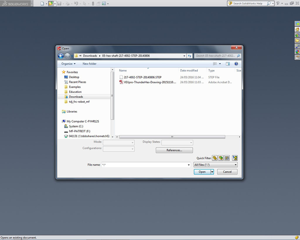
- Download the model STEP file and possible drawing specification file to a download folder, normally you will need to um-compress the file to view the STEP file. These files should be stored in a sub-folder with a descriptive name, such as shown, to later retrieve if necessary
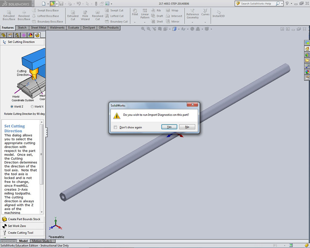
- Click yes on Import Diagnostics, then click on the green check mark, this is to check to see if file checks out
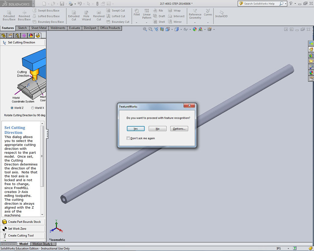
- Automatically you will also get a window pop-up asking if you want to proceed wit feature recognition, click yes,
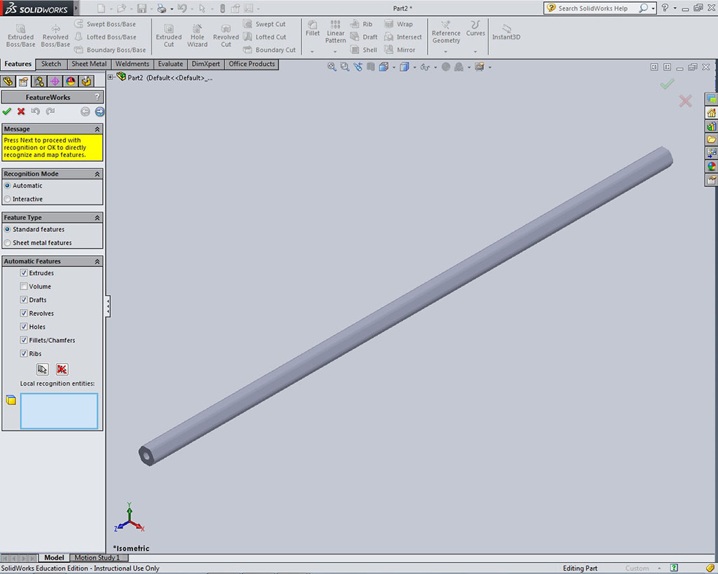
- Then if necessary in the feature works tab, select appropriate options and finish with clicking on the green check mark to initiate feature recognition process
- Once SolidWorks has recognized all the features and sketches, it will rebuild a new part file based original STEP file, which you can now use as a model part file to add to an assembly if needed
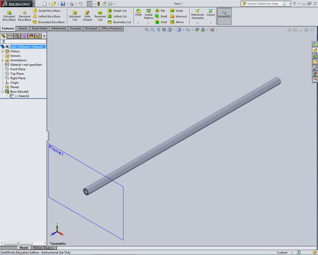
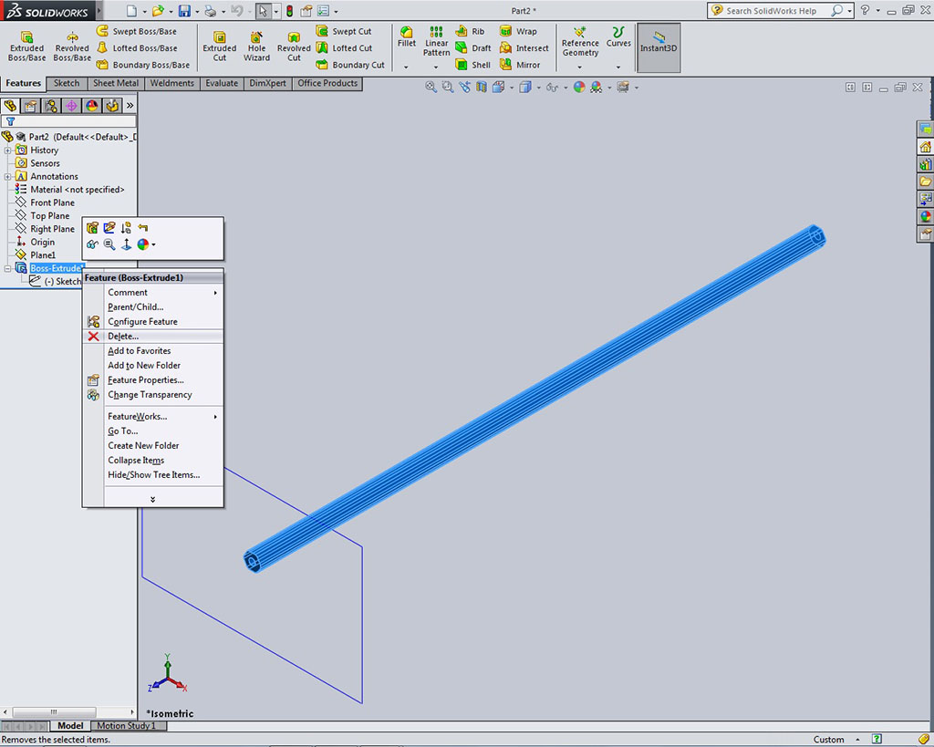
- First start by removing the Boss Extrude feature by right clicking in the tree on it and select delete
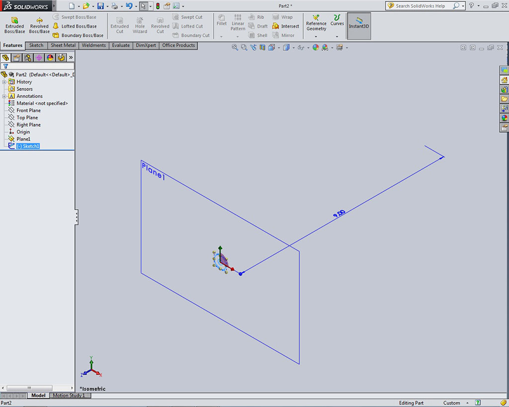
- In our example with the hex shaft sketch on a offset plane 1, 9 inches from the front plane and ideally best practice would be to move the sketch back to the front plane
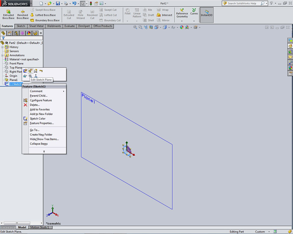
- To move sketch from plane 1 to front plane, ensure the sketch you want to move is below the plane prior to selecting the sketch, then right click on it and select the Edit Sketch Plane icon
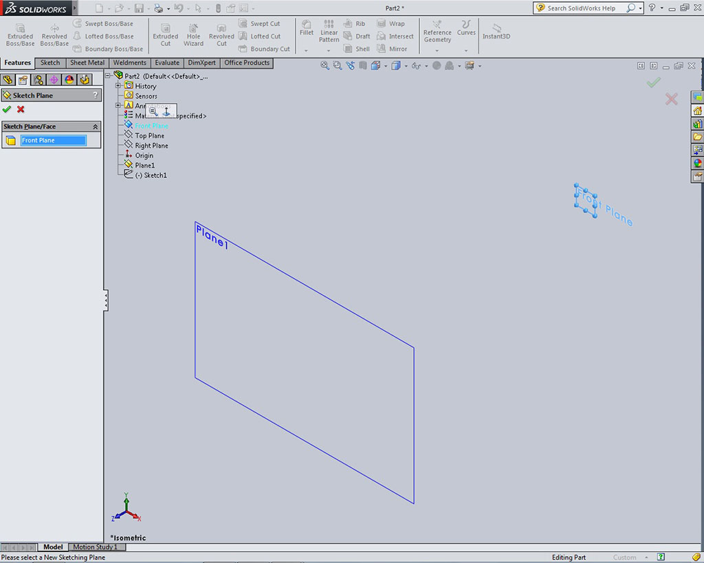
- Click on the plus sign on the external features tree inside main window and select the front plane to move 2D sketch, then click on the green check mark
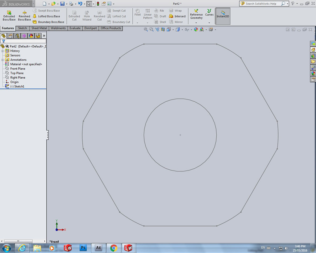
- Fit your 2D sketch in the main window
- Add your File Properties such as the description, etc for the part you are working on
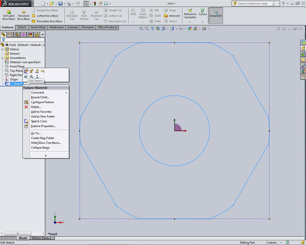
- Right click on your sketch in the feature manager tree and select Edit Sketch
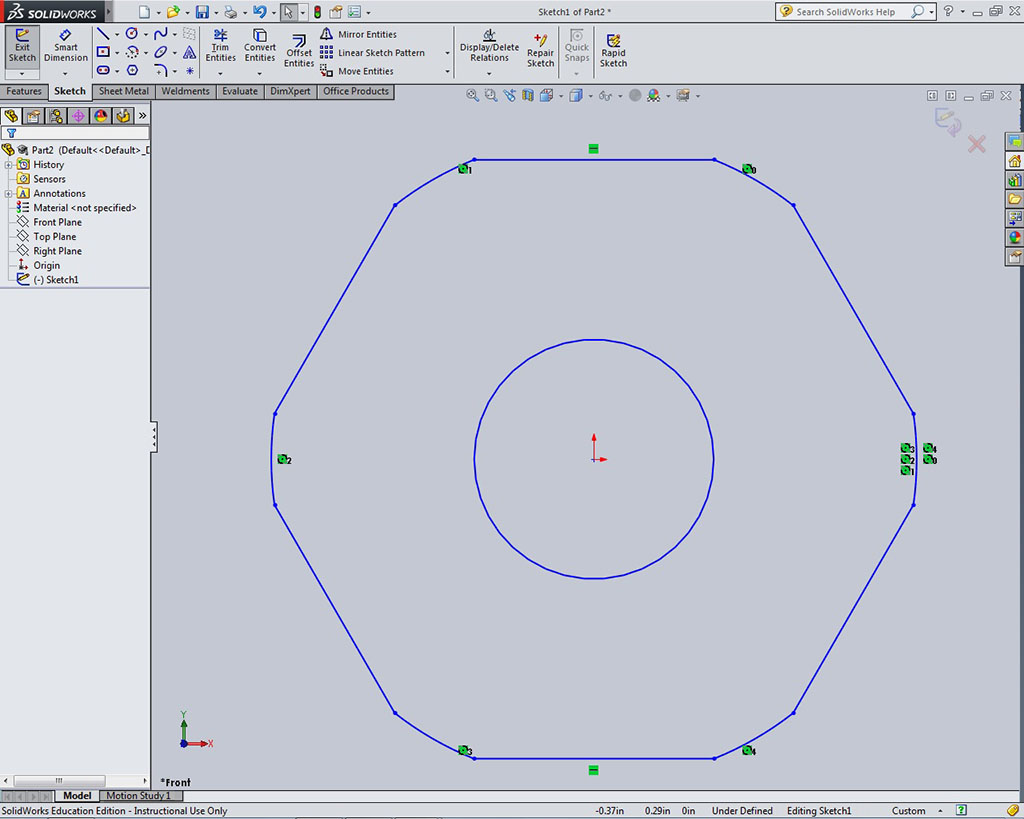
- At this point you should see any dimensions and relations your sketch has
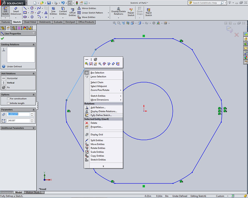
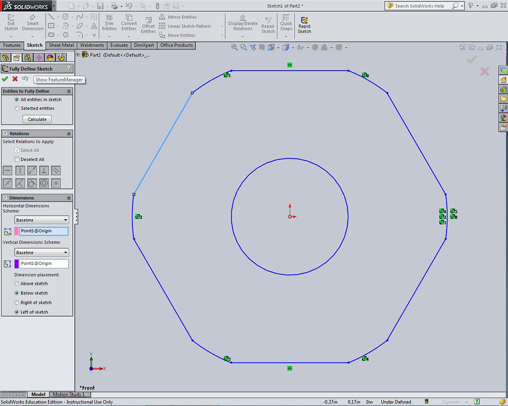
- Right click on any part of the sketch and select "Fully Define Sketch" and
- Ensure you have all the right options selected in the feature manager options panel, then click on the green check mark
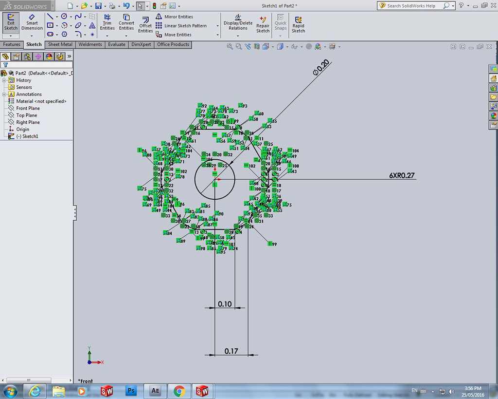
- Additional relations and dimensions will be added along with dimensions
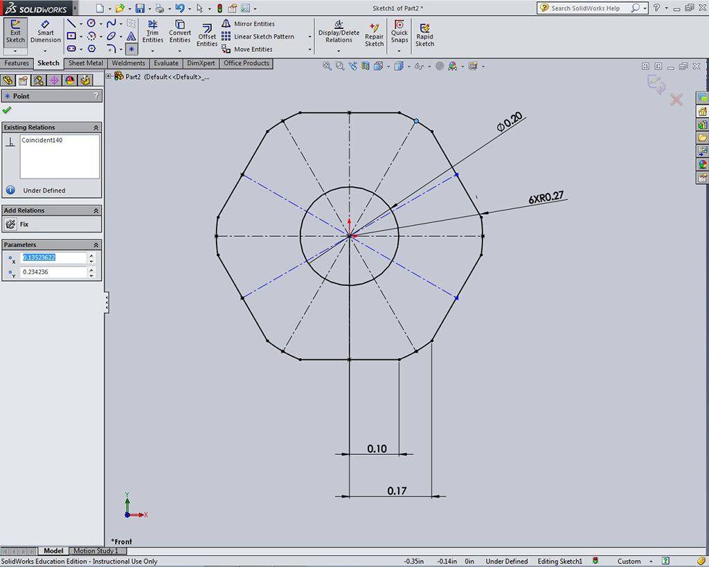
- Clean-up dimensions, hide relations if necessary, and finish adding possible construction lines and references for future use
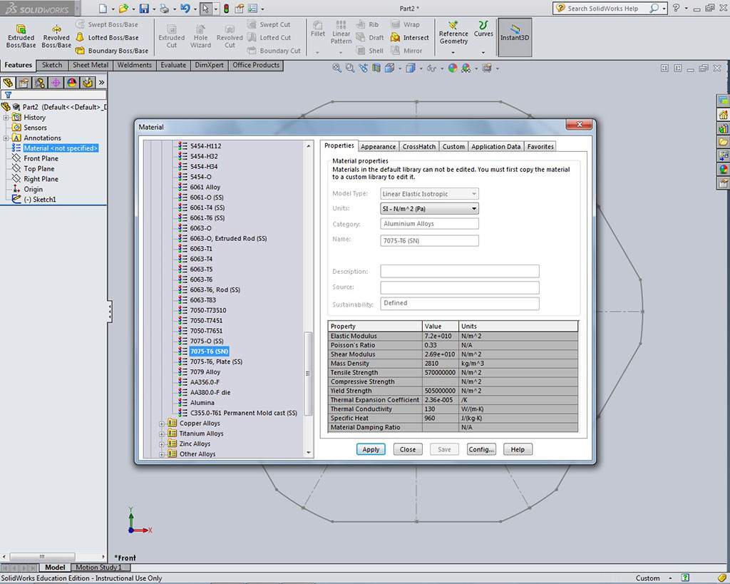
- Add material type in the feature manager tree, by right clicking and selecting edit material type, the add specific material, in our case, aluminum 7075 t6
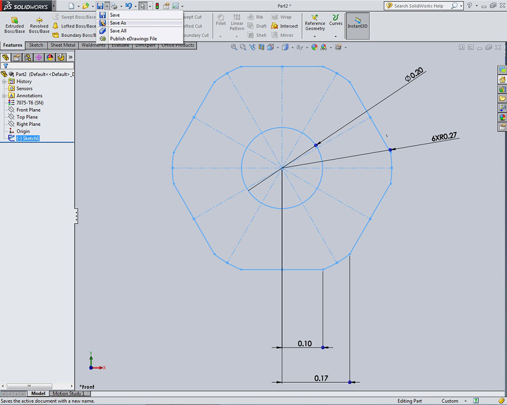
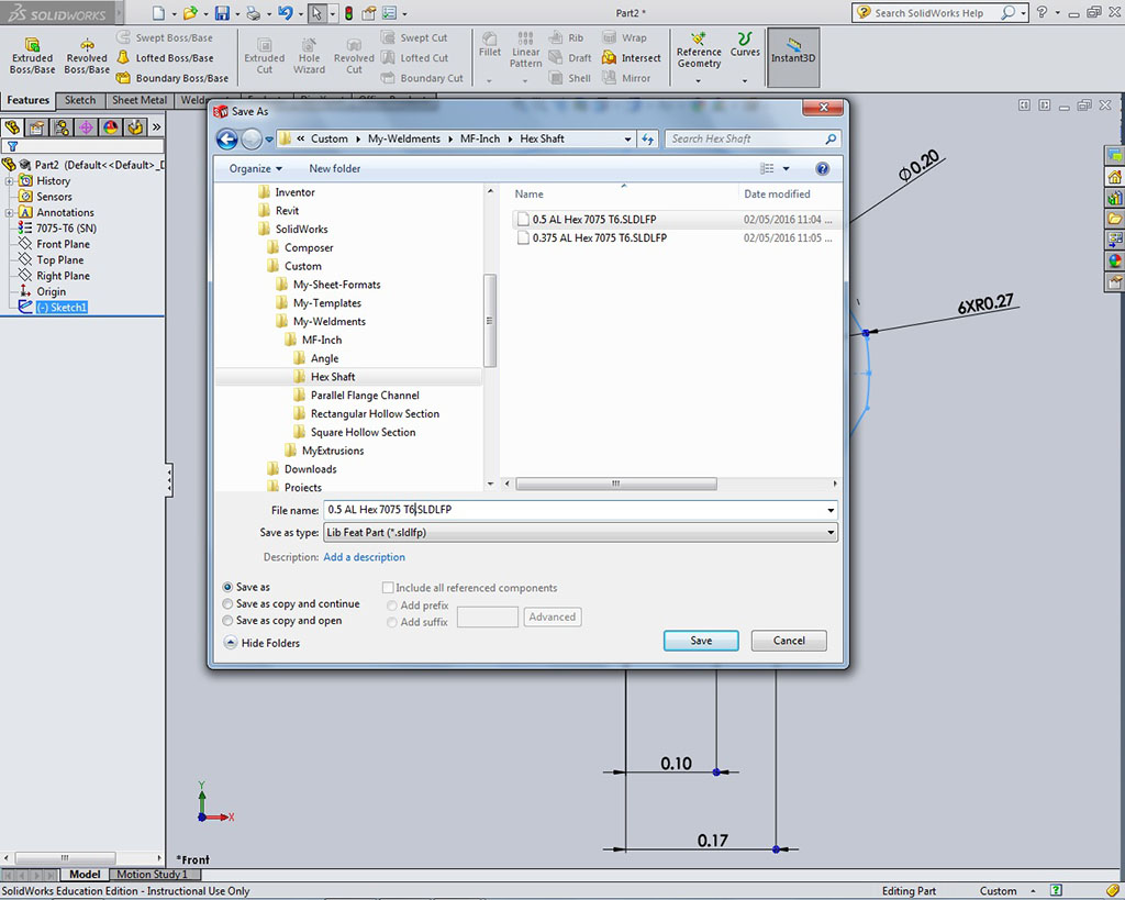
- Once you have all information in 2D sketch done, exit sketch, select sketch in feature manager tree, then Save As, and
- Save with appropriate file naming conventions with Library File Part selected as file type and locate your custom weldments folder and create a Hex folder for your new 2D weldment folder
Importing a STEP File
Step 1
Step 2
Step 3
Step 4
Step 5
Creating the Weldment 2D Profile from Imported Model File
Step 6
Step 7
Step 8
Step 9
Step 10
Step 11
Step 12
Step 13
Step 14
Step 15
Step 16
Step 17
Step 18
Step 19
Step 20
Importing, FeatureWorks, and Troubleshooting Resource Links
When you are using imported supplier CAD files, STEP files work pretty good and can usually be opened by SolidWorks and saved as a "dumb" SolidWorks part and/or assembly file. If you need control to edit that file it is possible to do some manipulation of the part file even if it is not recognized using the FeatureWorks tool. To get full control and edit the part fully, the imported CAD file will have to be recognized first using the FeatureWorks tool in SolidWorks. Be aware this does not always work and with our 2014 version of SolidWorks, as this version does not work well with Windows 10 in some cases, so some files will not work and result in an error and/or program crash. Several resource videos below go into detail on how you can manipulate imported CAD files.
- Importing a STEP File
- Typical process, 4.36
- FeatureWorks
- Importing-FeatureWorks, 3.21
- Using FeatureWorks, 5.27
- Working with "Dumb Solid"
- Editing imported models (dumb solid), 5.58
- Editing imports - FeatureWorks, 7.09
- Re-orient an Imported File, 4.57
- Importing 1- troubleshooting, 5.20
- Import Diagnostics (3), 7.01
Creating the Same Axle Weldment Profile From Scratch
For this same part that you require a weldment profile which the part can not be recognized in Solidworks and you were unsuccessful finding another part file that works, your next option is to use the original part dimensions/constraints to create a weldment profile from scratch. A lot of simple weldment profiles can be easily made from scratch and obviously should match standards that are used to manufacture, as your design needs to be based off of readily available standards that you can purchase and later build.
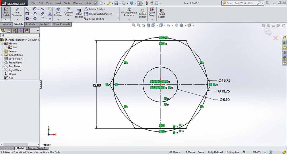
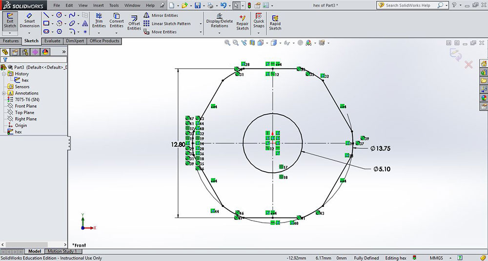
- Create a new part using a sketch with two circles, one internal shaft hole, one for outside shaft rounds, with appropriate dimensions based off original Thunder Hex drawing, then using the hex sketch tool, create the hex and constrain to fully define and update material, in this case 7075-T6 (SN)
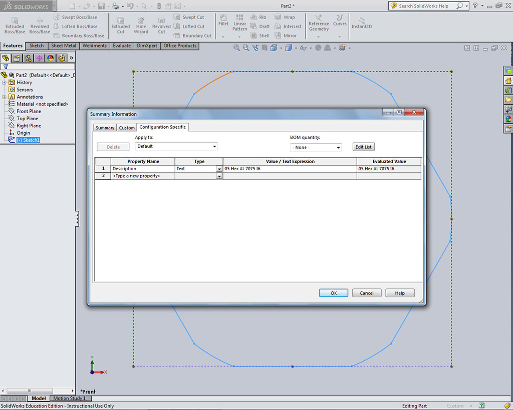
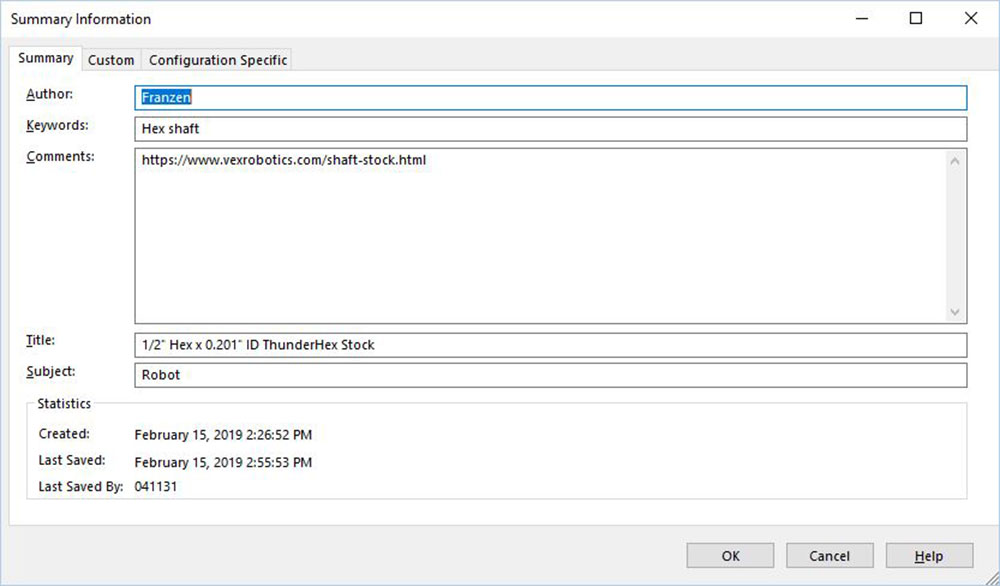
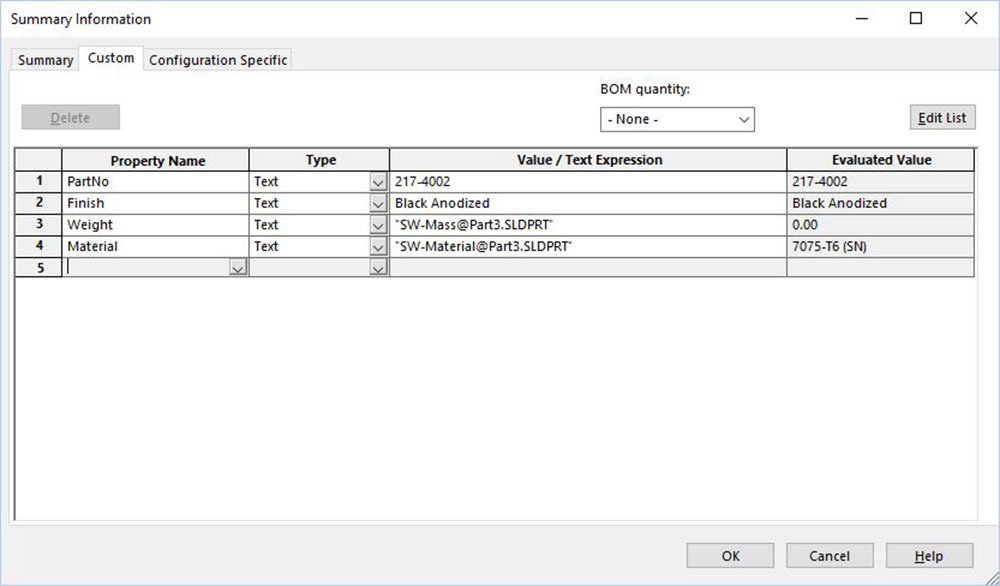
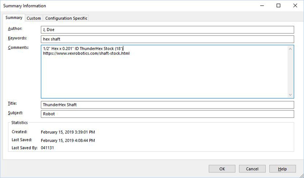
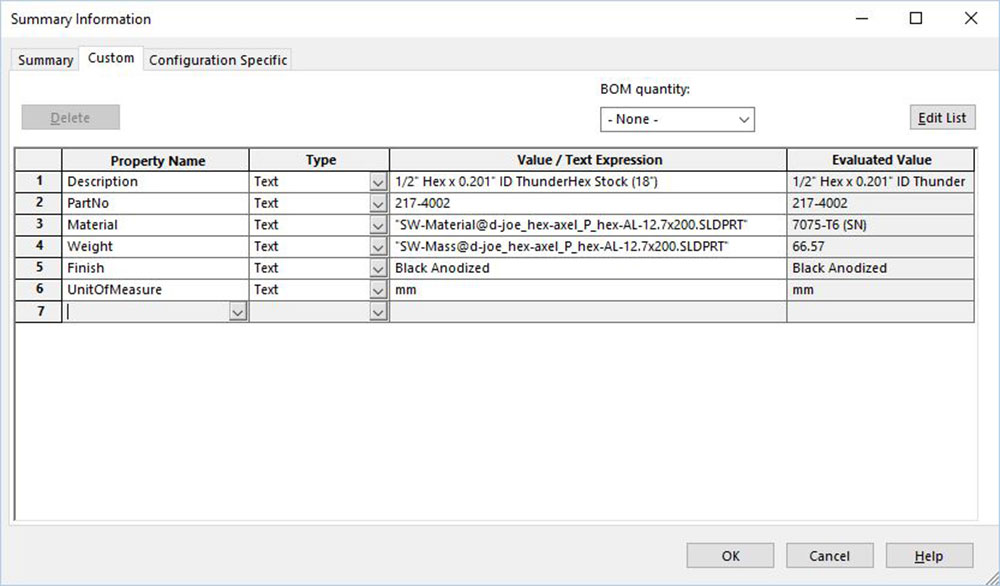
- Fill in Summary information through file properties menu or properties icon on top, as shown in an example
- In the same window next tab, fill in Custom information such as part number, finish, weight, material, etc (These two steps are good practices - newer versions do transfer this to the weldment and when creating drawings this information is handy when creating information tables)
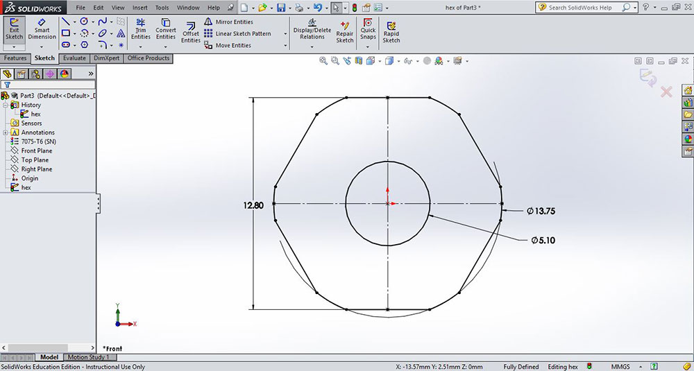
- Finish off your hex shaft using the Power Trim tool ensuring it is still fully defined, clean up dimensions if necessary
- Shows constraints visuals turned off, ensure you have sketch selected in the feature tree, then Save As, a library file part in the appropriate weldment profiles folder, as previously learned when doing the robot frame last unit. Remember to name your part files using the previously reviewed file naming conventions.
Step 1
Step 2
Step 3
Step 4
Step 5
Creating a Structural Model Part (the hex axle shaft) From a 2D Weldment Profile
Now that you have prepared a 2D weldment profile form a STEP file or created the profile file from scratch above, here is a quick review to create a model from the same 2D weldment hex shaft profile.
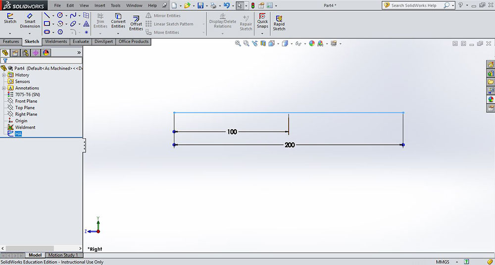
- To create the hex shaft weldment path, select the appropriate plane to sketch on, in this case the right side plane, and sketch your path and dimension the length to fully define it and if you want to centre it on origin a second dimension can resolve that
- Shows the system options file locations for weldment profiles.
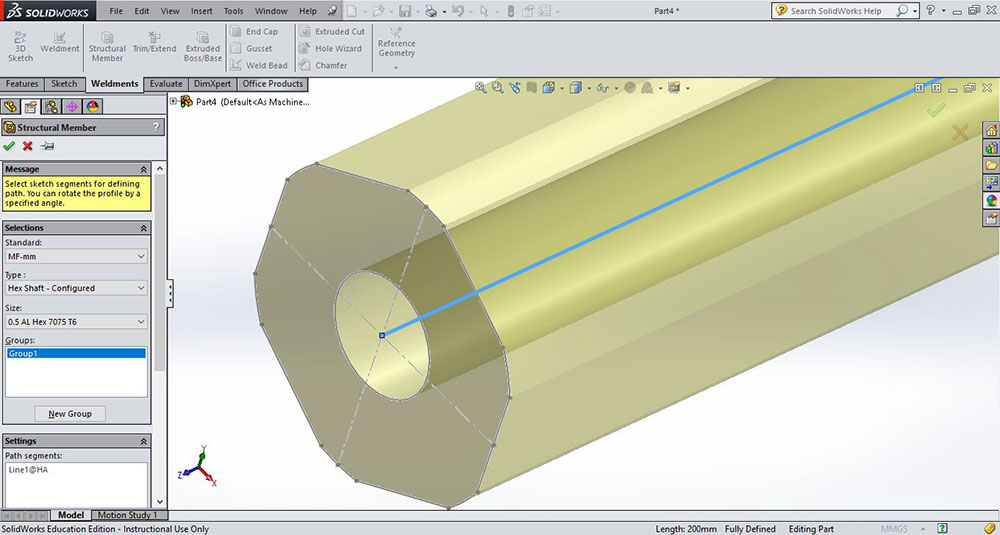
- Select the Weldments tab, then Structural Member, then select your weldment initial standards folder, then select the type folder, and then for the size folder, select your previously named 2D weldment sketch file. It is a good idea to angle the 2D weldment path in an isometric angle for future viewing
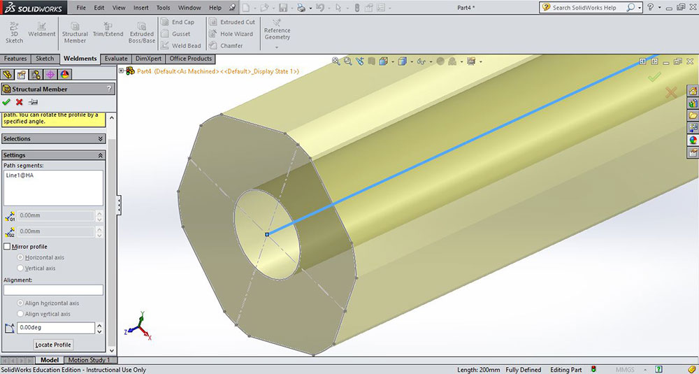
- With your 2D weldment sketch file selected, right click on the 2D path line for weldment profile to follow, a yellow preview will show. In some cases you may have to change the alignment, angle, or profile mirror to get it just right, in our case the centre reference is good, so click on the green check mark
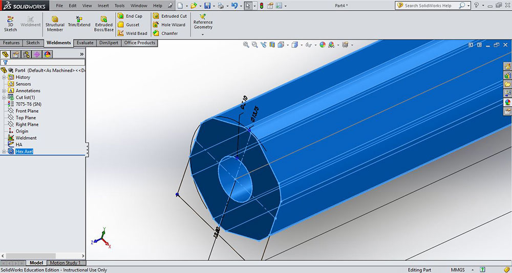
- SolidWorks will show a finished view of 2D weldment profile following 2D path. In newer versions, when you use 2D weldment profiles, it gives you the choice to also transfer the material type over, but for 2014 version you will have to add it again here manually
- Check or update your file properties summary and custom entries to ensure it has what is needed such as description, material, etc. This information is usually used later in tables - to identify characteristics of that part in particular related to other model parts and drawing auto-fill fields in the information block
- Use the Save As to save the weldment part file with appropriate file naming convention, and save to your robot root directory. As this is a part of your drive system, you could make and put it in a sub folder called drive system, or a better/recommended option is to just add the category drv to your file name such as td3-1_j-doe_drv_axel_P_HEX_AL_0.5x3.SLDPRT, so that later when you add more related drv models and assembly files, they are organized and will be easily found
Step 1

Step 2
Step 3
Step 4
Step 5
Step 6
Step 7
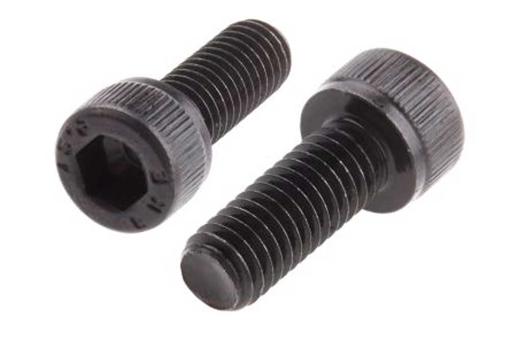
A little About Fasteners
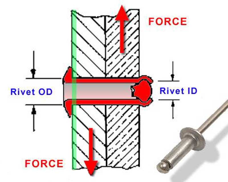
It is important to keep your fasteners for your project as few as possible in terms of types and sizes. Using a few common sizes on your bot will save a lot of frustration when doing repairs, finding tools, and keeping everything simple. For example, use a common rivet size that will work all over the robot. Using similar thickness sizing with rivets means you can make your rivet with a depth to cover common 1/8" or 0.125" sizing. This would mean you would need to make your depth 1/4" or 0.25". You also have the option to download common fasteners that you use from CAD suppliers online. Solidworks has an add-on called toolkit, which has a set of standard fasteners that you can also use.
Generally you put your fasteners on as the last thing as to not over complicate. It is simple enough to match hole from one object to another by using the tool "Convert Entities", and ensure that your mates are all good.
Create/Construct:
Sample Robot Drive System
The robot drive system requires you to build both of your wheels with the track wheel being more complex. Most of the parts are manufactured, so you will practice working with imported pre-made parts- not recognized and some that are needed to be recognized, because you need to modify for your own design, i.e. edit them for your own use/design.

For your convenience, you should find all of the components already downloaded into the pick-up folder under Resource Library\CAD\MF CAD Drive Sys Dwnlds so you don't have to search for them online. Also included in each folder are PDF support papers on each of the components detailing their specs and any other pertinent information.
![]() Remember folder/file use and naming convention, name features in feature tree, add the summary information, properties, and material for each of your custom parts made. Manufactured parts used, should be in the school networked share CAD folder library. Ensure you have your edrawing file: mf_drv-base_A_35x27.easm open for reference. Below are the basic steps to complete the robot drive system.
Remember folder/file use and naming convention, name features in feature tree, add the summary information, properties, and material for each of your custom parts made. Manufactured parts used, should be in the school networked share CAD folder library. Ensure you have your edrawing file: mf_drv-base_A_35x27.easm open for reference. Below are the basic steps to complete the robot drive system.
Steps:
- Be aware that in the PMT Pkg the material cost sheet has links for all of the parts, for example: to download the axle CAD STEP file, which you would normally use to create your own weldment profile for multiple weldment parts of the same shape, but in this case, will not recognize while other parts will work. Remember to keep-in-mind the sample folder structure picture, folder/file use and naming conventions section for organizing your robot CAD files before you start on the next step - i.e. keep this as a high priority throughout the project
- Because the STEP axle file will not be recognized since Windows 7 update to Windows 10, (ideal time to take a recognized part file to create a weldment profile), you will need to create a 2D weldment profile from scratch, then create a 3" drive shaft weldment part for the sample robot. Create the shaft spacer weldment profile- if it will not recognize with FeatureWorks, to use the profile, then you will have to also make from scratch - see eDrawing for spacer size lengths required for drive system
- Get or download the flanged bearing and import the STEP file with no part recognition as the bearing does not need to be edited or modified (plus an error will occur if you try to recognize it) and save as a SolidWorks part file for placement on robot frame assembly in step 5
- Create a drive system assembly file using your frame as the initial component and locking the frame model origin to the assembly origin (fixed). This is done by selecting it as your first part of your master assembly and click the green check mark without placing (clicking) in model/assembly space - this way the frame will by default automatically align/constrain to the origin. The other option is to manually do it by using mates to lock all planes of the assembly space to the component brought into the assembly using the the coincident mate tool
- Start by placing your bearings into your front, middle, and rear shaft hole locations with the bearing flanges facing to the inside of the frame (remember, have the eDrawings sample frame open, for precise view of part locations, placement, and position)
- Make sure you are building just the left or right side only, as you will later mirror the wheel model parts in the assembly to the other side using the front plane
- Start on Omni wheel assembly, by first opening the STEP file wheel assembly to save as an assembly to a sub folder, to keep parts organized and separate because this is a pre-made component with lots of parts, and better to keep all of those imported parts in a group. Also get the Versa Hub, and 25 tooth sprocket with hub will need to be imported to part files. Remember, FeatureWorks recognition is only needed if you need to edit that "part" specifically, you do not need to edit these parts as you are going to use as a "dumb" SolidWorks part file. You will also need the hex shaft and spacer weldments you made earlier
- Create a new Omni wheel drive sub-assembly using the axle as the fixed initial part, with appropriate mates to place and mate omni wheel sub assembly, hubs, spacer, 25 sprocket. Once all together you can take your Omni wheel drive sub-assembly and mate to your drive frame assembly - mating to bearings inside your robot frame (remember, just do one side, you will mirror later)
- Get the traction treaded wheel STEP file to save as an assembly. You will need to create the right wheel width by removing a tread and wheel frame ring after getting the STEP file saved as an assembly in its own folder. As this assembly will not have mates, suggest you "fix" all parts before editing assembly and just float those parts you need to mate for appropriate re-fit (not the norm, to have all fixed) then edit Torx screws, and hex wheel spacers or bring in new ones to position and mate as needed to end up with a completed 1.5" width traction wheel
- Create a new traction wheel drive sub-assembly with your hex axle as your fixed part and adding your updated 1.5" traction wheel assembly, the Versa Hubs, 25 tooth sprocket with hub, and hex shaft spacers, and then bring into your main frame drive assembly
- Download/get the gearbox STEP file and save to an SolidWorks assembly, the 16 tooth sprocket, and shaft clamps for adding to the drive frame assembly. It is important to align/constrain the gears from gear box shaft to the front and back gears for chain alignment (This will be checked to see if they are lined up and constrained to each other!). Before you mirror any sub-assembly components - front/rear wheel systems and gearbox, ensure there are absolutely no problems and all mating is done correctly, as mirroring it will compound problems/errors further
- Use the Mirror tool to mirror the front wheel sub-assembly, rear wheel sub-assembly and gearbox sub-assembly to the other side of frame using the front plane to finish your drive assembly. You will most likely have to work with the options and configuration of the mirror feature tool to get them mirrored properly
- Re-open each drive wheel sub-assembly, and create an exploded views in the configuration tab panel, spacing out each component appropriately for later use in showing in your drawings
- Now you are ready to create a drawing set as required in the Problem section above. Use the provided template and remember for the drawing information block fields to fill, you need to have those custom properties and the summary information correctly filled in in the related parts/assemblies
- Create exported JPG's and eDrawing files for your work completed, but it is not necessary for supplier CAD work - just work from scratch and work created from supplier CAD files
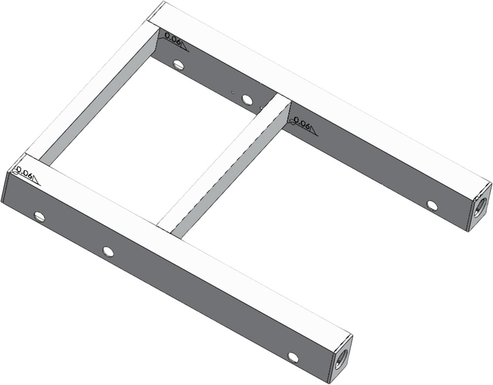
Frame
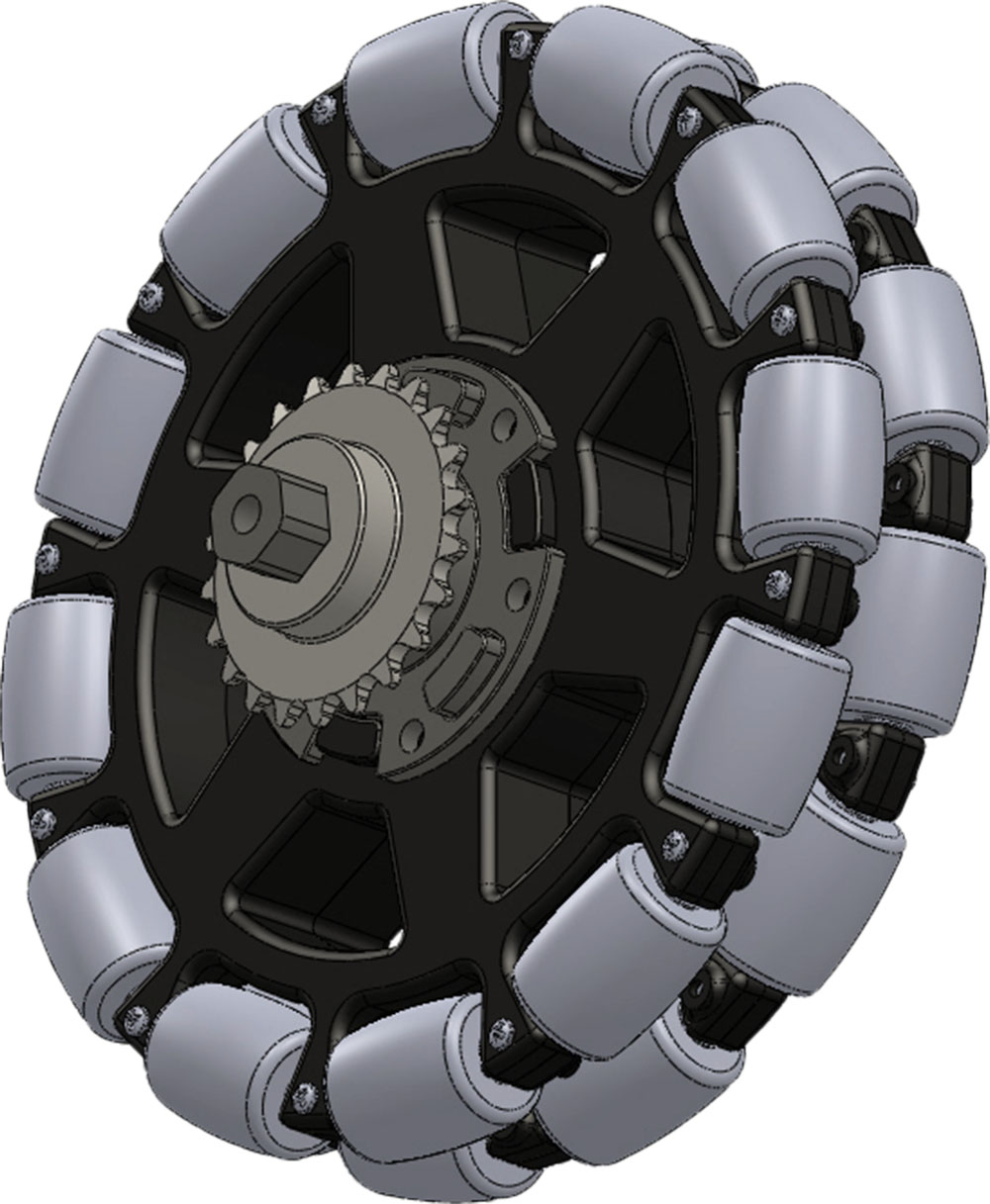
Omni
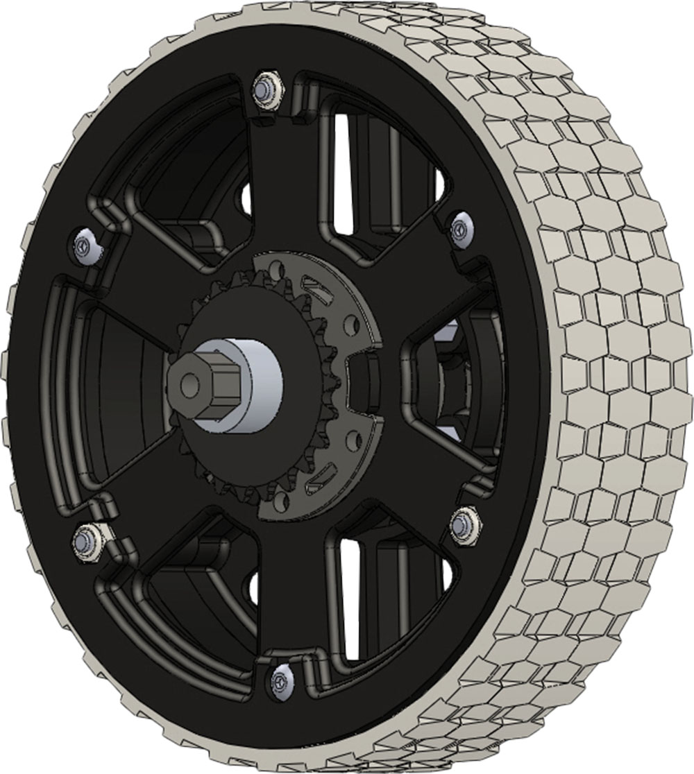
Track
Omni
Track

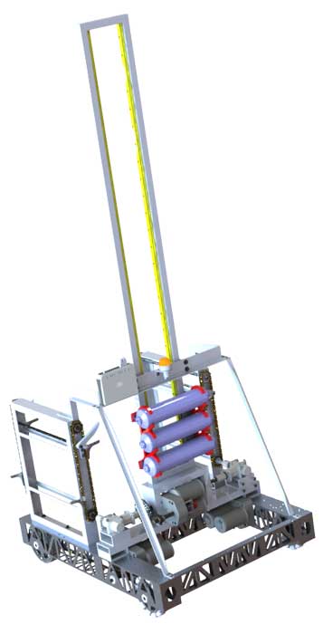
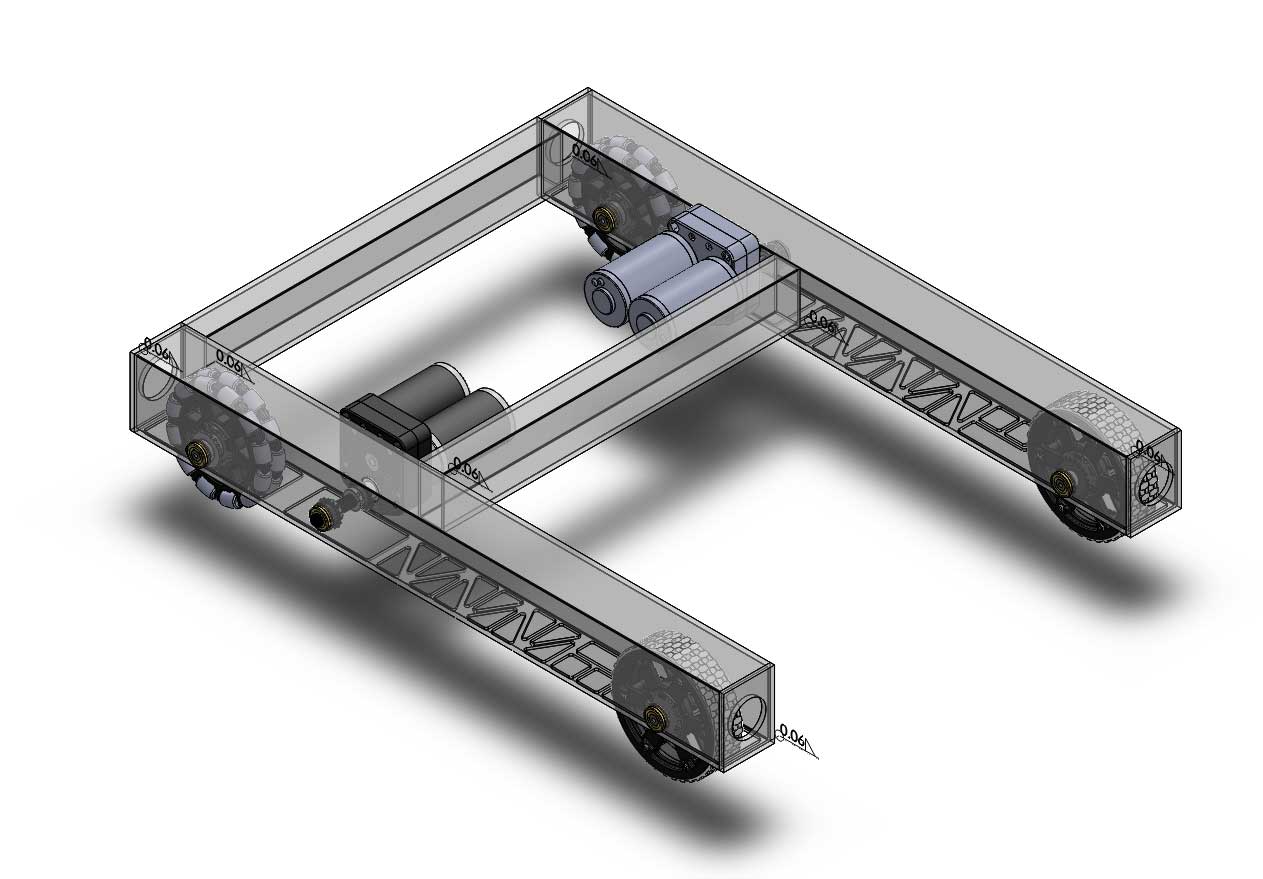
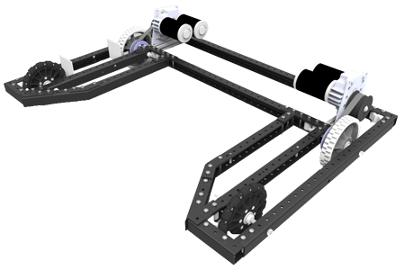
Drive System Assembly
![]() If you are stuck on something remember you can review related links in the Investigation section above and the previous unit, collaborate with your partners, and when done, use a peer to check your work before handing in, in hopes to find fixes and updates to improve your mark for this project.
If you are stuck on something remember you can review related links in the Investigation section above and the previous unit, collaborate with your partners, and when done, use a peer to check your work before handing in, in hopes to find fixes and updates to improve your mark for this project.

Custom Robot Drive System
Time permitted, using the above sample process, apply it to your custom robot, by adding your drive system to your frame, creating your assembly, exploded views, then creating a set of drawing sheets and an updated cost material sheet
Evaluation:
You are responsible to hand in your sub-assembly drive system as a separate folder for evaluation, with the master assembly (that which holds all the sub assemblies together- drive system, elevator, gripper intake, etc) will be looked at in Unit 6.
Make sure your folders, files, organization, and naming conventions are saved correctly, files open up to appropriate views (for example model part and/or assembly - full screen with best ISO view), all CAD files working (double check parent files if you have changed file/folder names), and include full page JPG images and eDrawings of all CAD work completed. Ensure you have completed the SolidWorks Self/Peer Checklist sheet when you hand in your digital CAD files. This self/peer evaluation sheet (worth 10% of project mark) and is there to help you hand in the best product showing your process build, get written feedback on your completed work, and a mark breakdown.

| Evaluation Breakdown Component Descriptions | Marks |
|---|---|
| Always double check that you have completed all components for full marks. | |
| Axle - finished axle model part from 2D weldment profile process | 15 |
| Drive System - Sub & master assemblies,, exploded wheel views | 50 |
Unit 4, Act. 2: Tote Elevator Lift
Situation:
With base and drive system complete, further functions can be created and added to the robot design. The main function for this robot is the ability to collect the totes and stack at the same time, so something would have to be designed and created.
Problem/Challenge:
Using the provided edrawing file on the elevator, create the elevator frame using weldments, then add the hex shaft, latch stop, and pneumatic cylinder to get the basic elevator assembly together. Some parts will have to be made from scratch, while other parts will be provided in the school class CAD library folder. For the advanced step, finish by also creating the latch lift and chain components to finalize the elevator design. Once done, the elevator can be added to your master assembly already holding the robot drive frame and drive system, mirroring to the other side, and fasten.
Investigation/Ideas:

Design Ideas
Coming up with a working design requires a lot of time and effort to ensure you have considered all intricacies of your design. Below show some sketches with a lot of ideas, calculations, and direction based on what you will be drawing in Solidworks. Be aware that these are based on finial iterations, as previous ones are not shown here.
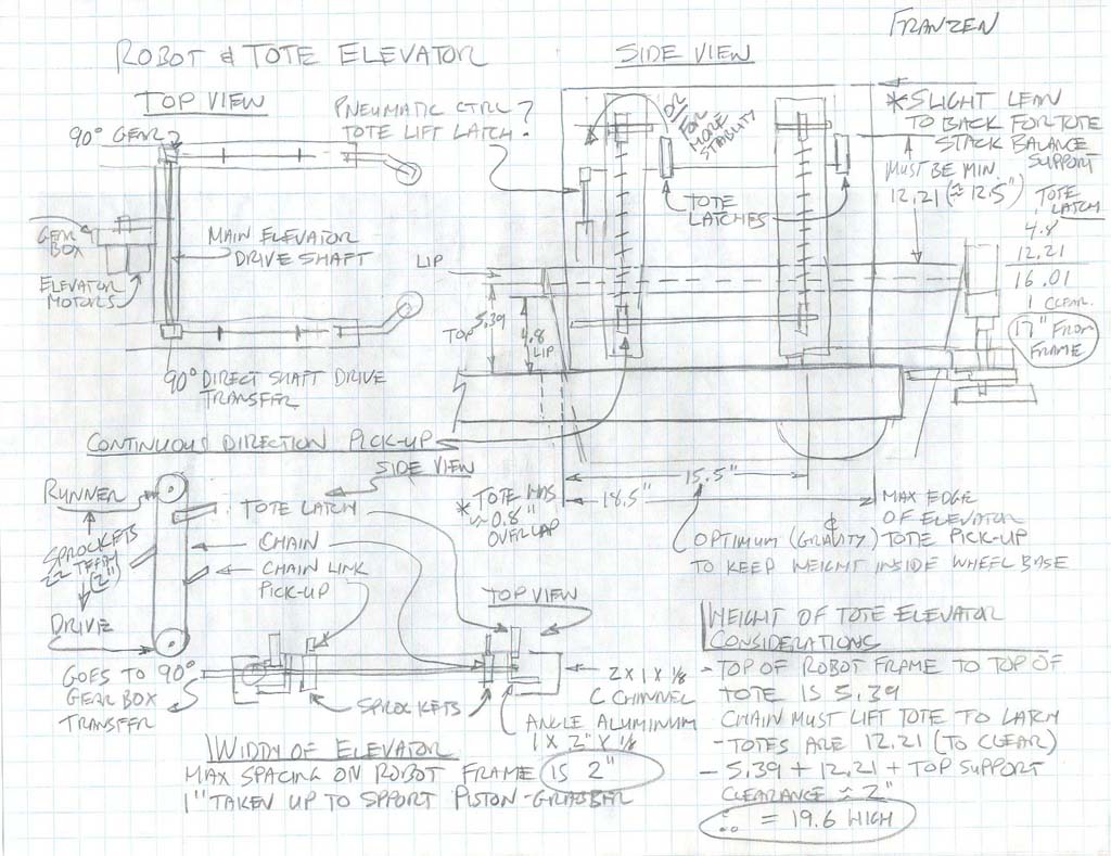
Elevator Ideas 1
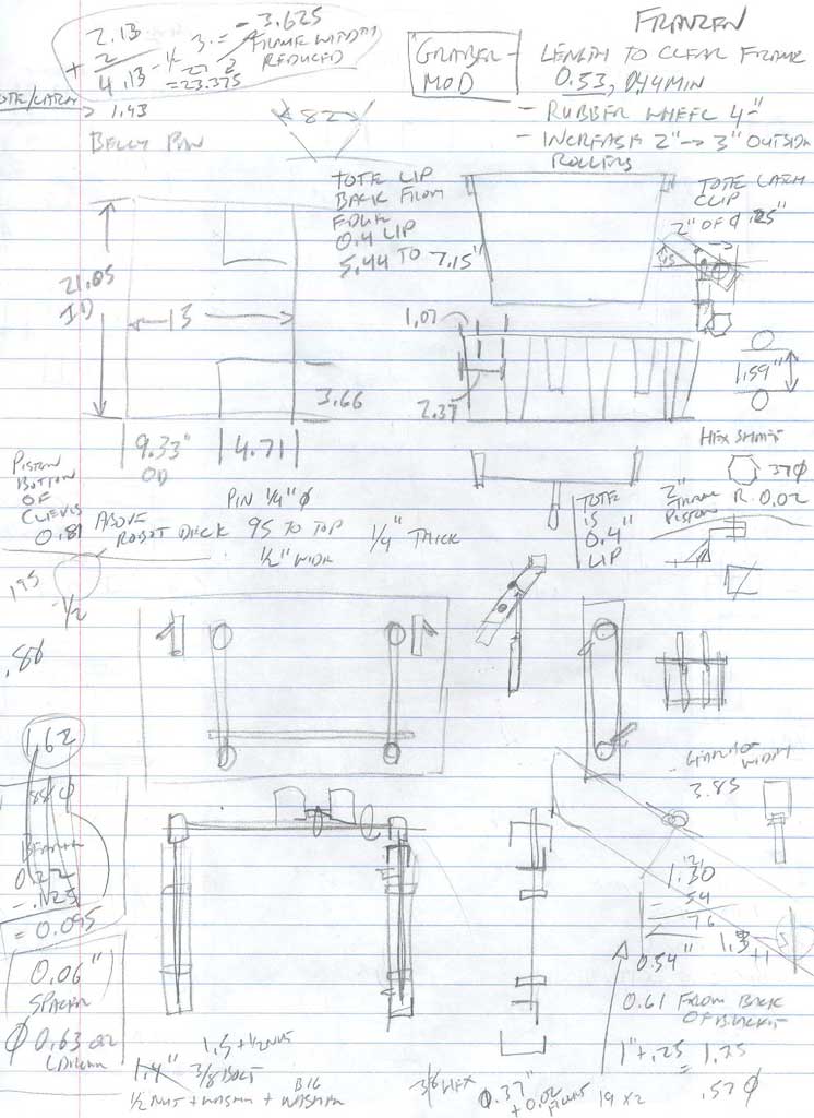
Elevator Ideas 2
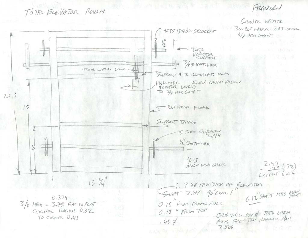
Elevator Ideas 3
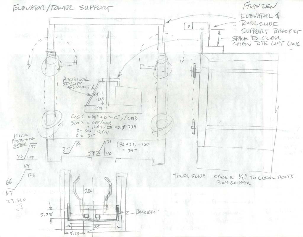
Elevator Ideas 4
Components to Consider
When you see files names starting with mf-... means this is usually a custom part made from scratch. Parts that have part numbers or are not following normal naming convention most likely are from a suppler. Weldment profiles use the same naming convention with the exception of not showing course and name, just the name, size, shape, and material. Below show the weldments, manufactured, custom parts, and advanced components for the tote elevator function as an example.
Weldments to consider on the tote elevator:
- Weldment profile 2.0x1.0x0.125-AL-Au-6061T6.SLDLFP
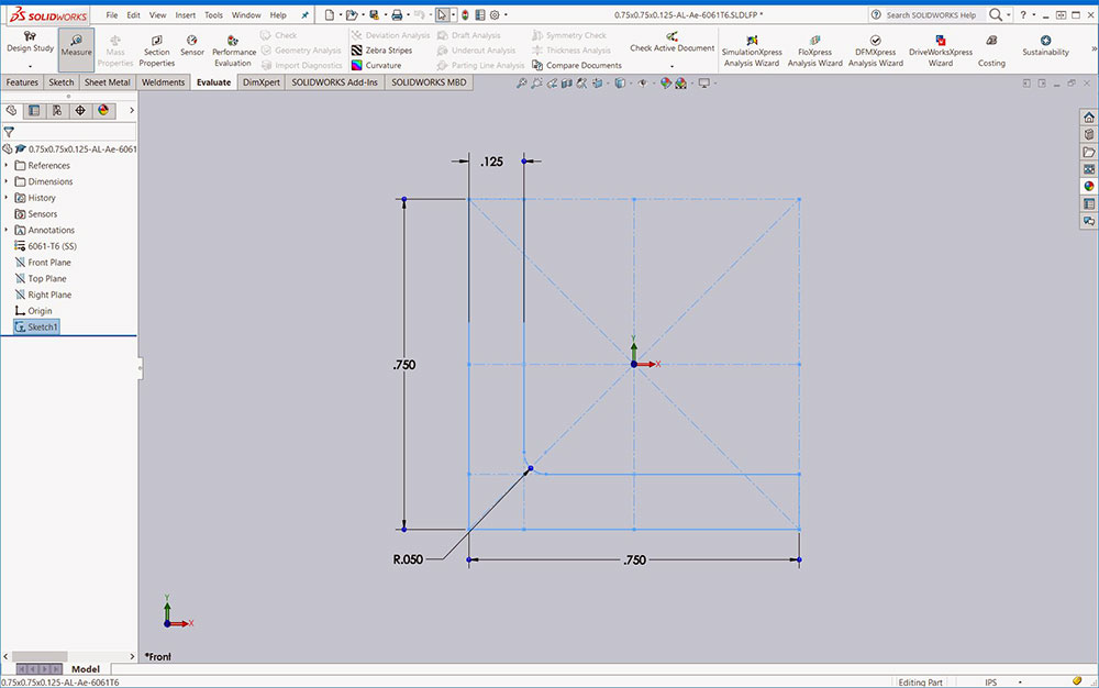
- Weldment profile 0.5x0.5x0.125-AL-Ae-6061T6.SLDLFP
- Weldment profile 0.5 AL Hex 7075 T6.SLDLFP
Manufactured parts to consider on the tote elevator:
- Bearing Flanged ThunderHex 217-4006 - 13.75mm half-inch x 1.125 x 0.313.SLDPRT
- Shaft Collar Clamping 1-2in 217-2737. SLDPRT
- shaft cir-clip Ext 3-8in Shaft 0.352in grove0.029in 97633A170.SLDPRT
- sprocket 35 w Hub - 15t - 1-2in Hex ID 217-2660.SLDPRT
- Bimba pneumatic piston: elev-latch-piston-020_5(F,D-770)(F,D-850).SLDASS
Custom parts to consider on the tote elevator:
- mf-elev-tote-latch-base2.SLDPRT
- mf-elev-tote-latch-base-stop-support.SLDPRT
- fastener-rivet-domed 0.25dia 0.251 to 0.375.SLDPRT
- mf-elev-tote-latch-piston bracket-inner.SLDPRT
- mf-elev-tote-latch-link.SLDPRT
Advanced parts to consider on the tote elevator:
- Custom: mf-elev-tote-latch-link-ext.SLDPRT
- Custom: mf-elev-tote-latch-link-pin
- Manufactured: Chain Attachment Link Sk-1 Tab n35 7321K330.SLDPRT
- Custom: mf-elev-tote-latch-link.SLDPRT
- Custom: chain link single 35.SLDPRT
- Chain created with belt tool using above chain links
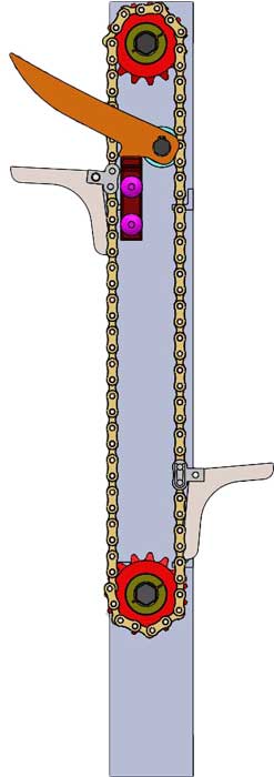
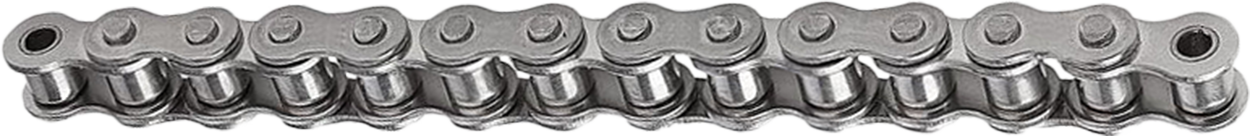
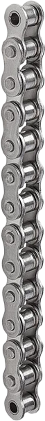
Creating Roller Chain
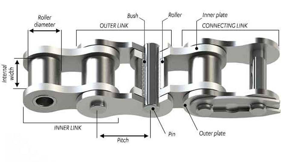
Creating chain in Solidworks can be done using the Belt/Chain tool in the Assembly Tools feature tab. It can be difficult the first time creating a chain, is more a visual than practical, and can create unnecessary file size and complexity to your model design files. In the case of the tote elevator, a special link is used with a custom latch lift part, and is difficult to see/understand without the chain in place. Normally just creating the path for the belt/chain path is practical and useful to ensure sprockets or pulleys line up. In order to do this, it is important to mate one pulley at a set distance on shaft, then mate the second pulley/sprocket from the first one, so that they are exactly lined up. Two common sizes used in FIRST robotics are:
- #25 chain is sometimes known as 1/4" pitch chain, since the links are 1/4" apart
- #35 chain is sometimes known as 3/8" pitch chain, since the links are 3/8" apart
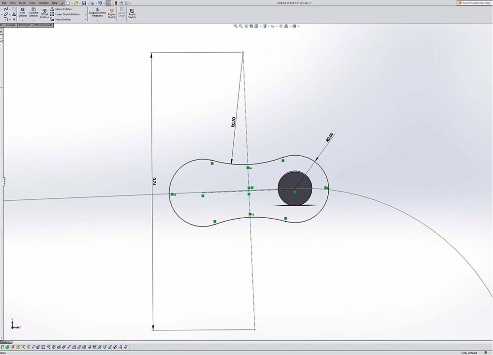
Sketch link
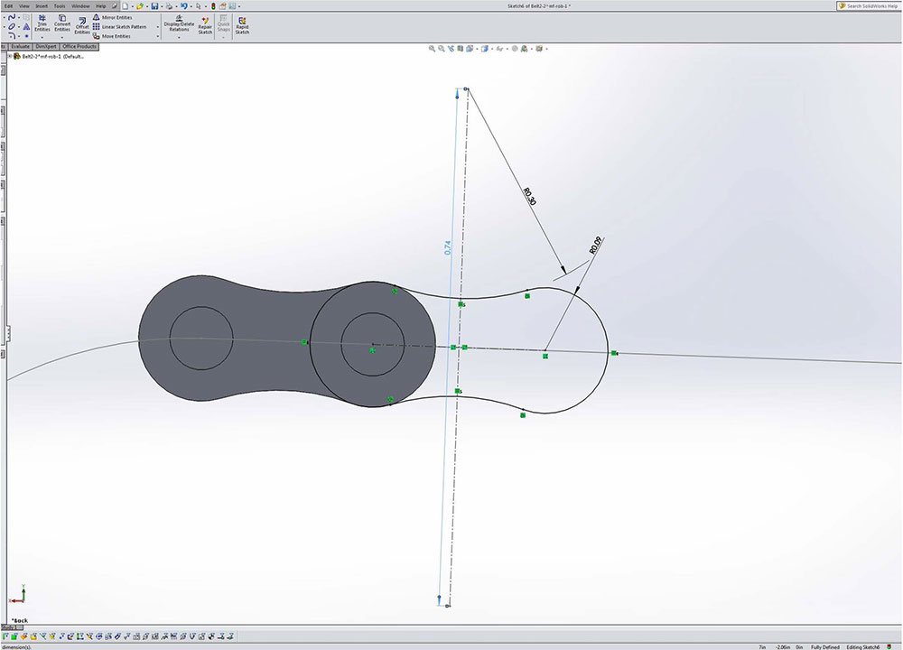
2nd link
Other side
Link done
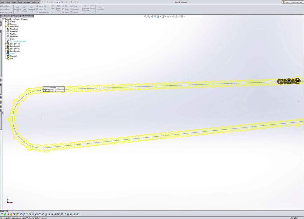
Curve pattern
Belt/Chain Creation Steps in Solidworks
These steps below can also be followed in more detail in Solidworks Chain Tutorial video, (6 min).
- Create a mid plane to create belt line
- Use Assembly feature tool Belt/Chain tool to create between both sprockets and select the circle for the first sprocket and the face of the second gear, with mid plane just created selected, ensure in properties tab Engage belt is not checked, green check mark
- At this stage your belt/chain loop is done, but for visual purposes, a chain or belt can now be created on the belt loop line
- Belt is found in your feature tree with a sketch and a part, open up the part, and look at sketch and select front plane
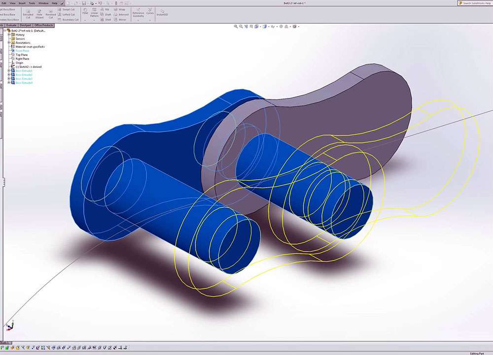
- Create a circle on the belt loop line and extrude out mid plane for the diameter and length of chain roller
- Create 4 circles on the front plane, first centre of roller, 2nd one on belt loop line and two more perpendicular between the two just drawn with connected construction lines locked on their mid point relations
- Set an equal relation for opposite circles and then size up each circle to represent the outer chain side plate sizing
- Once chain side plate is sized correctly, then create a offset and blind extrude to set the outer chain side plate thickness and location on roller
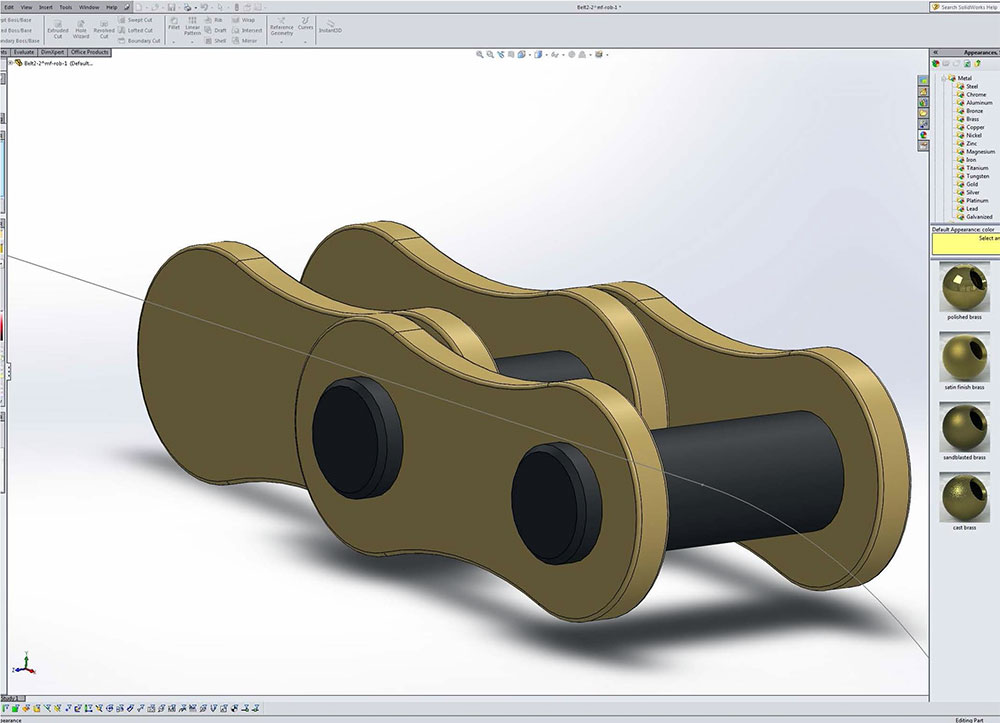
- Create the second roller using the first roller to work from matching size
- For the inner plate, make another sketch on the back or inside of your outer plate with the same concentric sizing and extrude inner plate with a small offset
- Now that you have half done, you can mirror using the front plane the outer and inner chain plates to the other side of the rollers, and ensure Geometry Pattern is selected in the options tab before clicking on green check mark. At this point if you wish add material, appearance, etc.
- Select the Curve Driven Pattern from the Linear Pattern tab, select your Mirror, add the appropriate number of instances in your Directions 1 tab, check Transform and Tangent to curve, and under Options tab check on Geometry pattern, select green check mark
Related Resource links
- Roller Chain Specs
- Kinematics on Creating Belts and Pulleys (5.18)
- Path Length Dimension (2.11)
- Belts and Chains (2.54)
- Calculating Roller Chain Length
- Roller Chain Calculation Basics
Create/Construct:

Tote Elevator Lift Build Steps
You are to create one side elevator, as you will later be mirroring to the other side of the bot later. Use folder/file use and naming conventions, name features in feature tree, add the summary information, properties, and material for each custom part made.
Below are the basic steps to complete the tote elevator lift.
- Create required weldment profiles for you angle aluminum
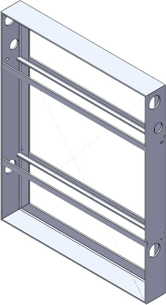
- Create a weldment frame part for one elevator side which includes both aluminum angle sizes (used double small angled profiles to create small angle cross support pieces)
- Add holes for bearings, bottom mounts, and latch base support rivets
- Create from weldment profiles the two 1/2" chain drive sprocket hex shafts and the 3/8" latch stop hex shaft
- Create mf-elev-tote assembly by bringing in the frame on origin as fixed
- Add your bearings, shafts, sprockets, collars, and cir-clips.
- Custom make your elevator tote latch part, add to axle latch stop hex shaft in mf-elev-tote assembly
- Custom make your elevator tote latch stop part, add to mf-elev-tote assembly with holes and rivets
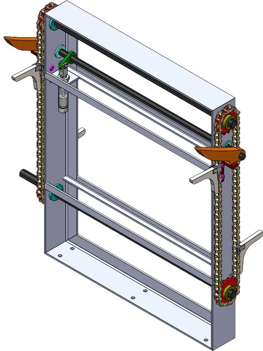
- Custom make the piston bracket-inner to support Bimba pneumatic piston and tote latch link that fits on 3/8" latch stop hex shaft
- In mf-elev-tote assembly, mate tote latch link, inner flat bracket, and piston. Piston subassembly will have to make flexible in the feature tree -component properties or in assembly tool bar. This will allow you to mate appropriately to see virtual movement of attached piston, latch link, and shaft
Front
Side
Top
Latch
Cylinder
Adding to Master Assembly
With mf-elev assembly completed, this can now be added as a sub assembly to the master assembly made up of the fixed frame drive system and this created elevator.
- Start by creating a master assembly with the drive frame as your fixed sub-assembly keeping in mind the front view of your finished robot design, i.e. place showing side of drive system with frame opening to the right
- Next bring in your tote elevator sub-assembly and locate/mate to top of drive frame
- Add mount holes on drive base using convert entities from tote elevator base for mount bolts
- Mirror your elevator sub-assembly using your front plane
Further Advanced Build

Elevator DWG
This part involves the chain, chain link attachment tab, and custom tote latch link if time permits.
- Start by making the custom tote latch link
- Making the chain will involve making the chain link and the pin, then using the belt tool to create the chain pathway
- With chain made with the belt tool, you can remove one of the links and mate your chain attachment tab link, pin, extra chain link
Evaluation:
You are responsible to hand in your sub-assembly as a separate folder for evaluation, master assembly will be looked at in Unit 6.
Make sure your folders, files, organization, and naming conventions are saved correctly, files open up to appropriate views (for example model part and/or assembly - full screen with best ISO view), all CAD files working (double check if you change file/folder names), and include full page JPG images of all CAD work. Remember when you hand in your SolidWorks project, make sure you have completed and handed in the SolidWorks Self/Peer Checklist sheet also. This self/peer evaluation sheet (worth 10% of project mark) is there to help you hand in the best product showing your process build and get written feedback on your completed.
| Evaluation Breakdown Component Descriptions | Marks |
|---|---|
| Always double check that you have completed all components for full marks. | |
| Profiles - working for use with weldments in tote elevator frame/axles | 15 |
| Tote Elevator Basic - completed and on master assembly | 40 |
| Tote Elevator Advanced build - Chain and latch lift | 20 |
Unit 4, Act. 3: Elevator Middle, Upper Frame Support and Gripper Tower

Situation:
With the main tote elevator mechanism done, it will need support and a drive system to run it. It makes sense to focus on the related function before working on/ creating another function.
Problem/Challenge:
Finish the elevator system by completing the elevator drive, support frame, and tower. Stacking totes must be quick, robust, and efficient to maximize the ability for speed. It also must have torque to handle the load as it collects totes, as each additional tote adds to the weight that has to be pushed up.

Investigation/Ideas:
3D Sketching for Weldments
As you have already sketched using the 2D sketch tool to create several weldments. For basic shapes that the sketch only needs to be on one plane, 2D is fine, but once selected/started drawing in 2D you can't switch to 3D, so you need to select before hand to get the three point sketch feature. Note it is possible to add additional planes manually to your 2D sketch then continue the sketch on another plane, but is far easier to just use the 3D sketch tool. With a lot of custom frame components that look the same from a mid point, design the one half in 3D, then once finished adding your features to you 3D sketch, you can mirror making both sides symmetrical with half the work.
Resource Links
- Extruded Frames,(16.58)
- SolidWorks Weldments 101 - Simple Table, (16.44)
- Creating Custom Weldment Profiles, (5.30)
- Guide to Solidworks Weldments
- Editing Weldment Profile Custom Properties, (2.56)
- SolidWorks Weldments and Frame Stress Analysis, (20.10)
- Advanced 3D Sketch Techniques Part 1, (9.40), Part 2, (8.34)
- Simple Tips for Modeling Springs
- Compression Spring on Solidworks, (7.41)
Create/Construct:

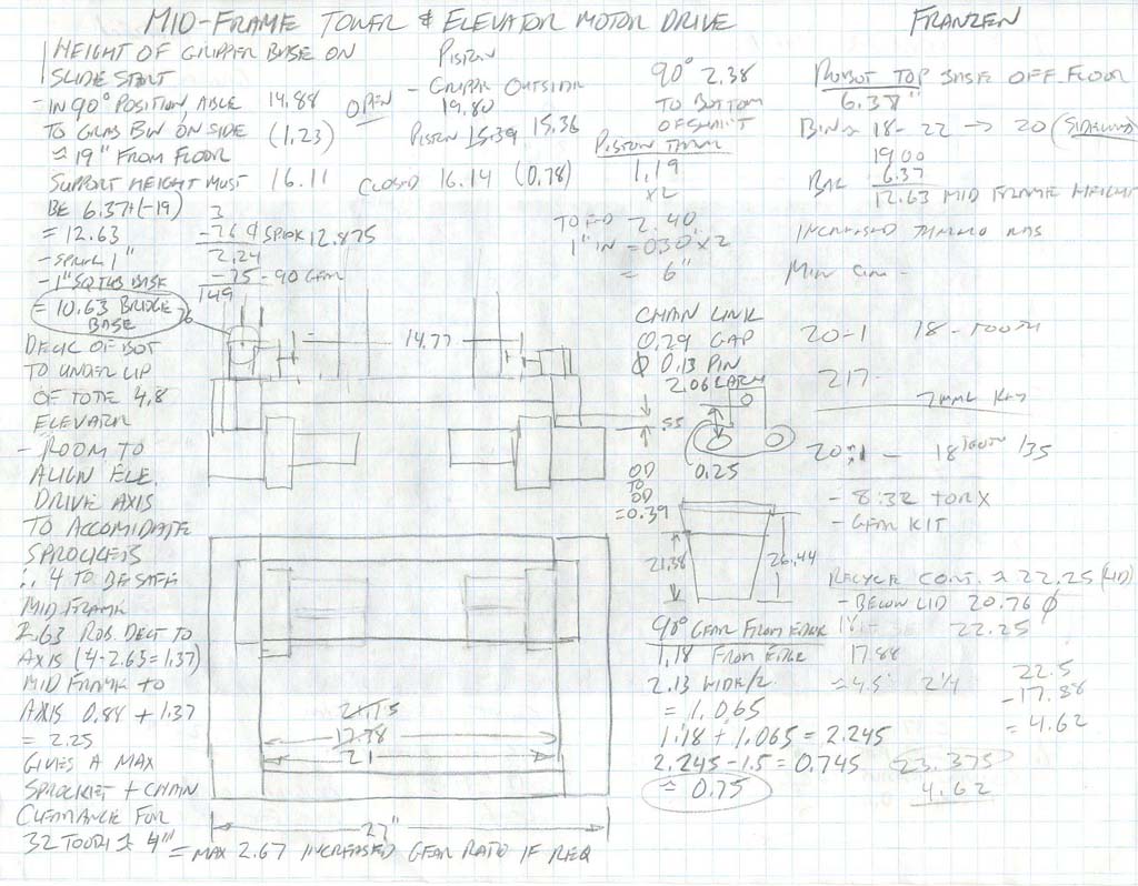
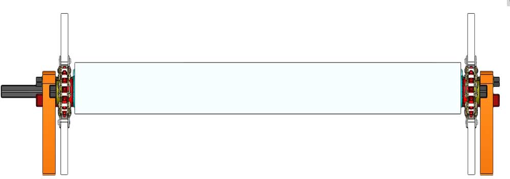
Mid Frame Sketch
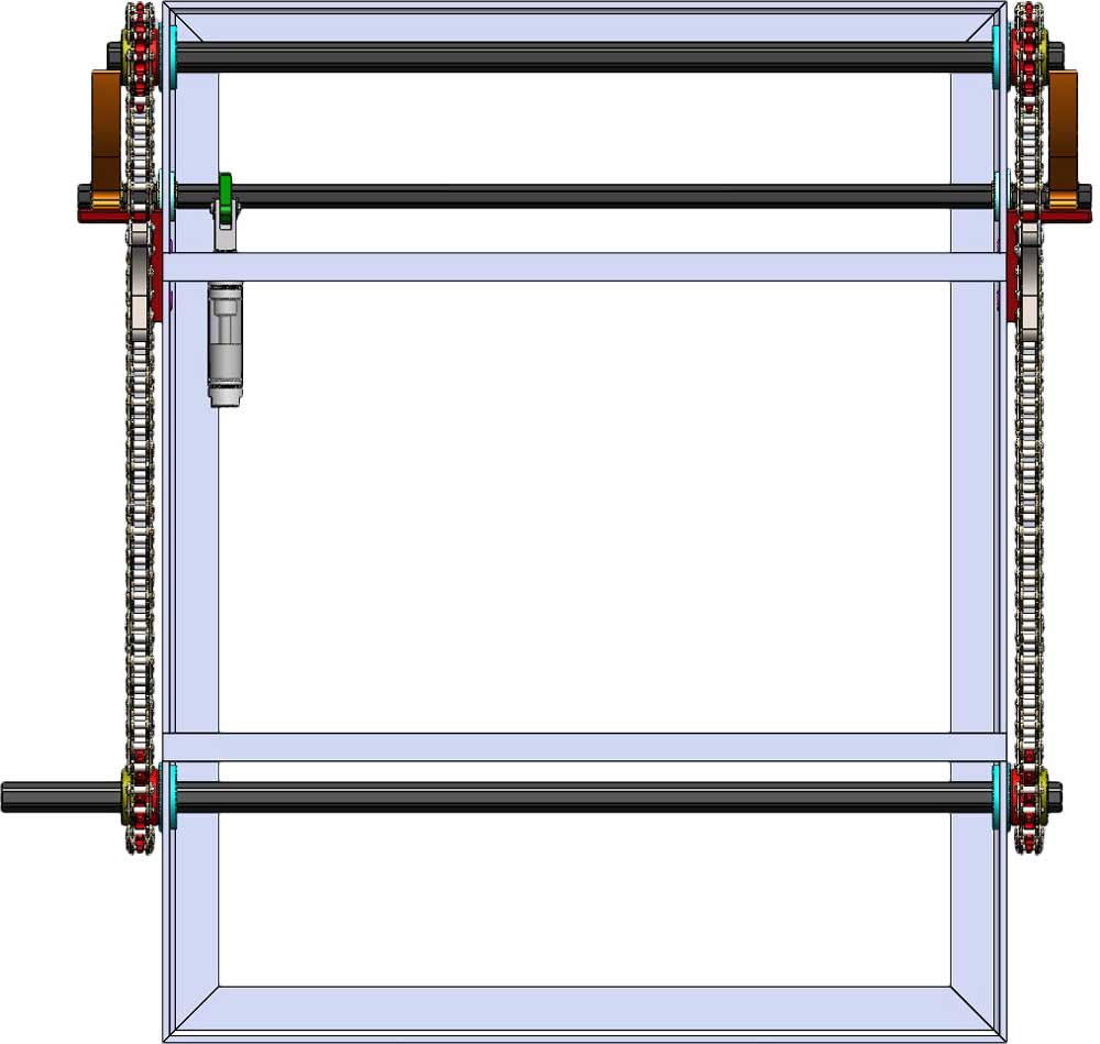
1 Elevator Mid Frame Drive System
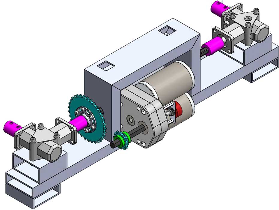
This elevator mid frame and drive system is what will run the two side tote elevator tote lifts. The rotation drive was placed horizontal to frame, connecting from a smaller sprocket off of drive gear box to larger sprocket to increase torque and reduce speed rotation. Rotation direction was changed using ninety degree gear boxes on both ends, thereby driving sprockets and chains on both side tote elevator lifts.
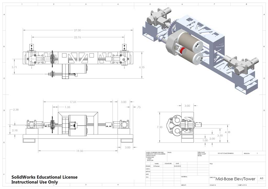
Mid Frame DWG
Remember to use the related eDrawing file found in your school class folder to see assembly and part details. Manufactured parts used should be in the school networked share CAD folder library. Below are the basic steps to complete the elevator mid frame drive system.
Use folder/file use and naming conventions, name features in feature tree, add the summary information, properties, and material for each custom part made.
Step to Build
Below are some of the basic steps to get you started.
- First step is to create a rectangular hollow section (RHS) weldment profile: 3.0x1.0x0.125-AL-RHS-6061T6.SLDLFP
- Create a 3D sketch for the mid frame
- Add to frame spacers for your first structural member
- Finish mid frame with new structural members to complete you mid frame part
- Cut out square holes for tower vertical columns, to be added later and also the hole for elevator hex drive shat in centre
- Create another RHS profile: 3.0x1.5x0.188-AL-RHS-6061T6.SLDLFP for a weldment structural member spacer under the two-way 90° 2:1 reduction ratio gear box
- Start adding same drive gear box used earlier for robot drive system wheels by using a coincident mate to align face of gear box to frame and a parallel mate to align with frame and two distance mates for positioning
- Add the two-way 90° 2:1 reduction ratio gear box assembly/part (does not need part recognition as no editing needed) on the one side and fasten first using the "Convert Entities" tool to line up holes and torx cap bolts washer and nylon hex nut (Note, you will mirror the other one later as shown)
- Other parts to finish adding, include; the hex shaft (weldment), hex shaft couplings, two sprockets and versa hub, shaft collars
- Last step is to mirror the two-way 90° 2:1 reduction ratio gear box, RHS spacer, fasteners, and hex shaft couplings
- Add to master assembly on bot frame as a sub-assembly
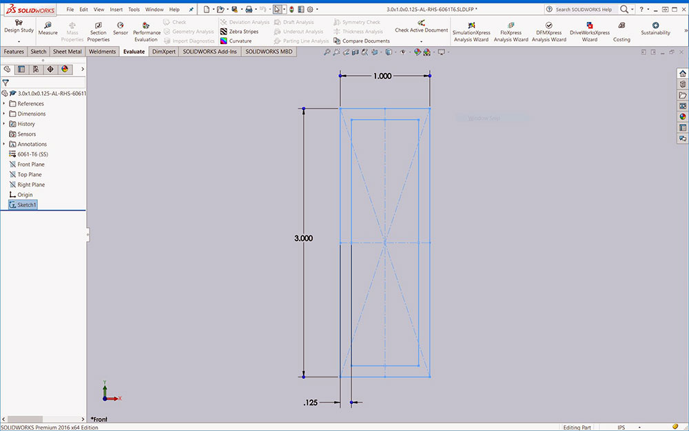
RHS profile
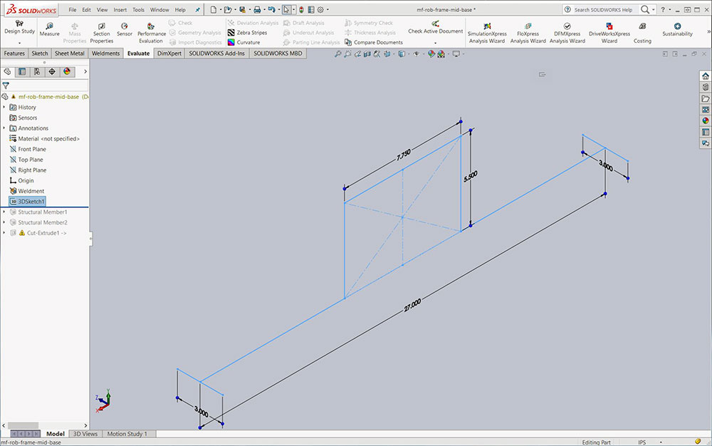
3D sketch
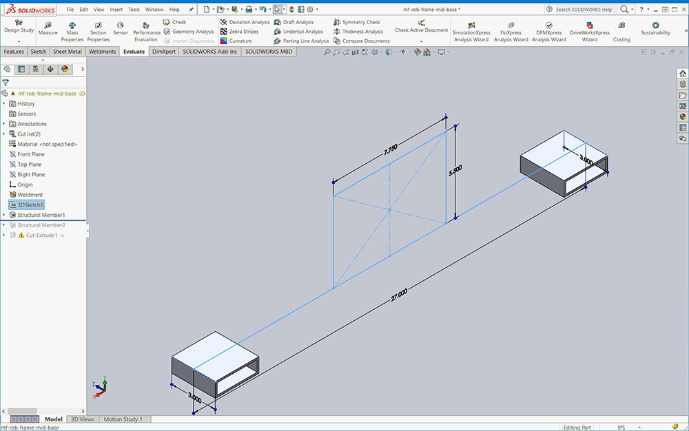
1st structure
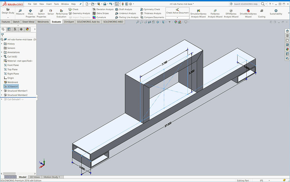
Completed
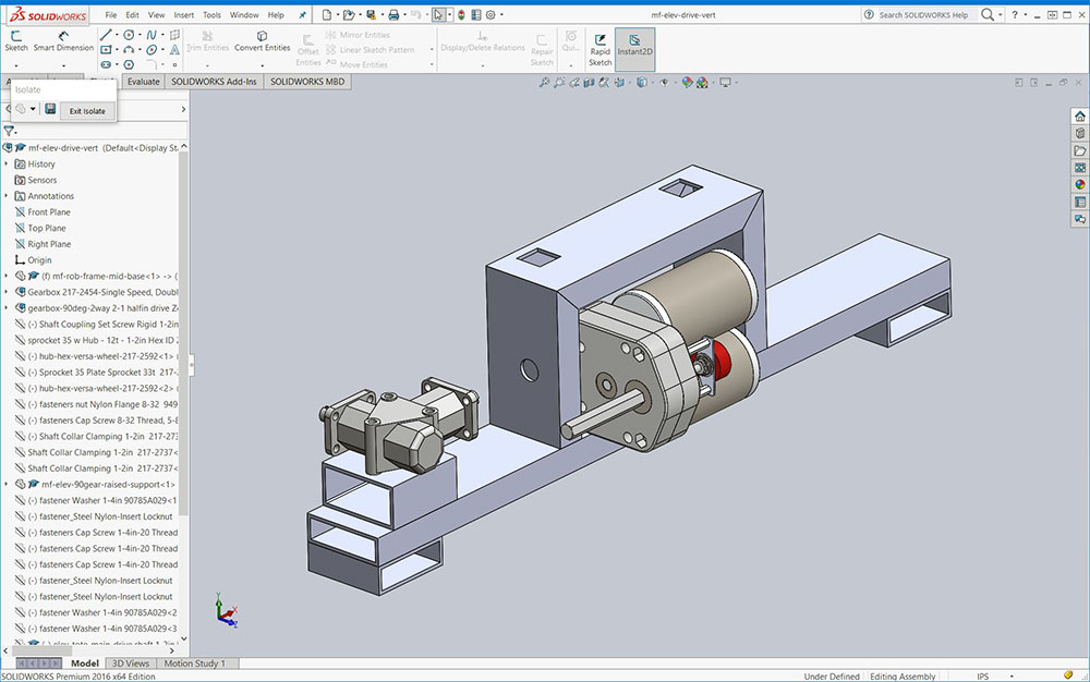
Components
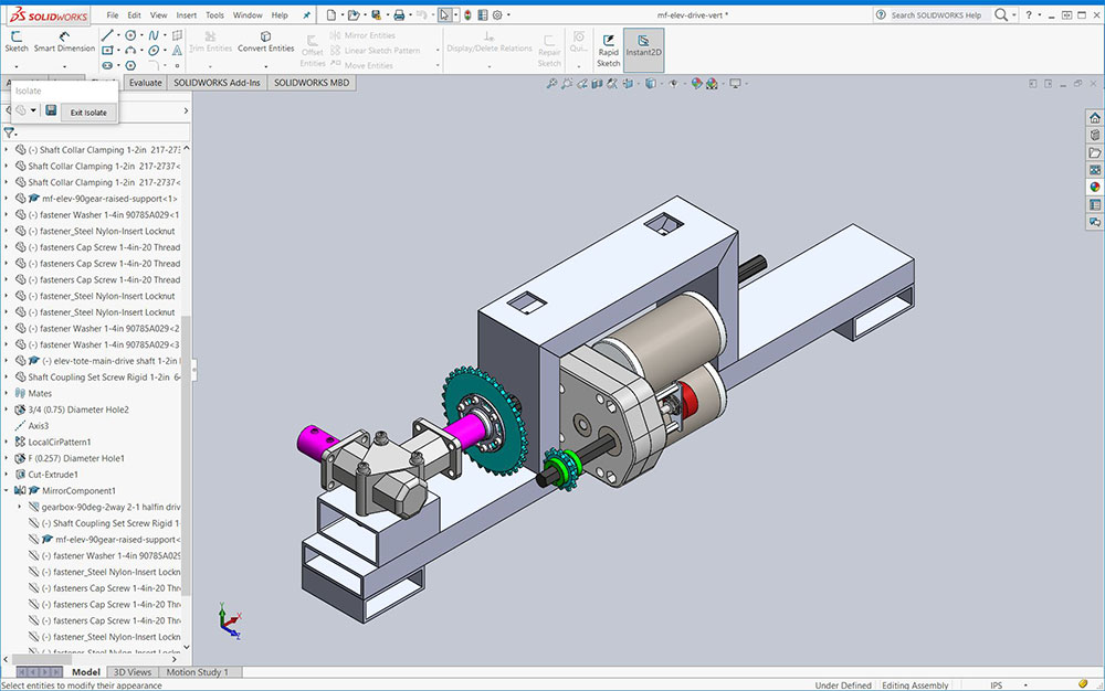
Components

Front View
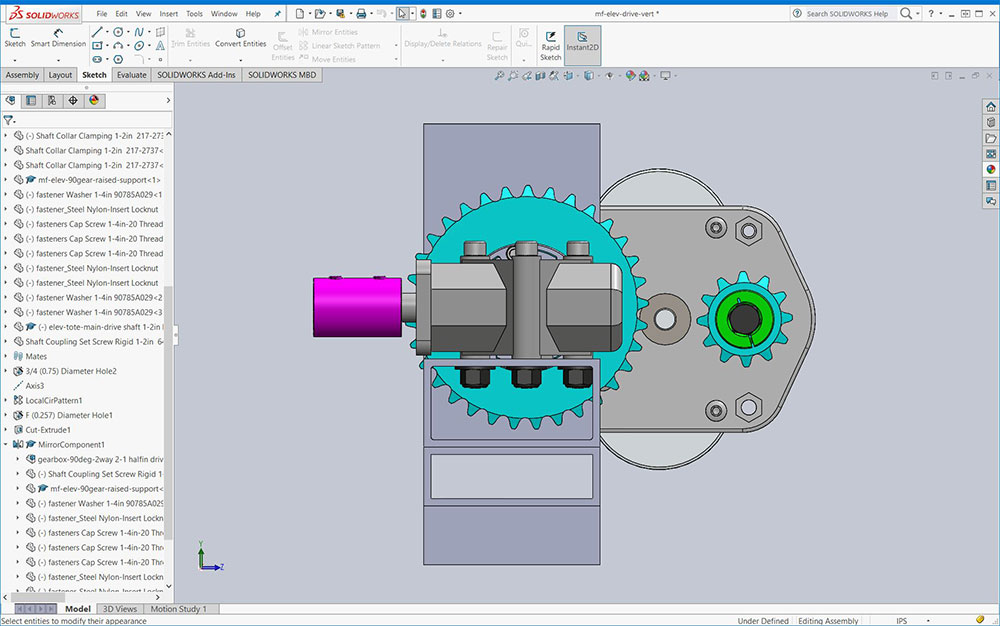
Side view
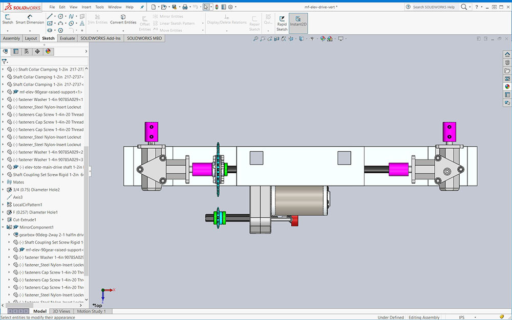
Top view
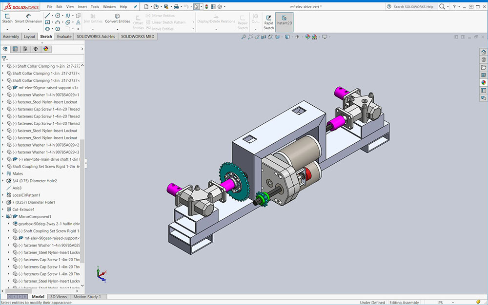
ISO View
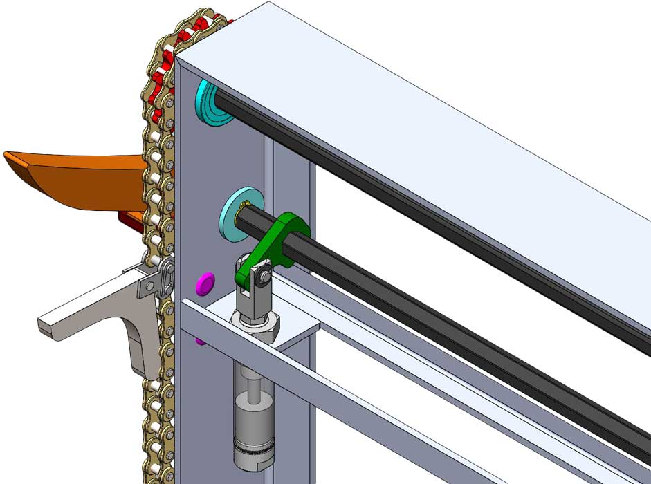
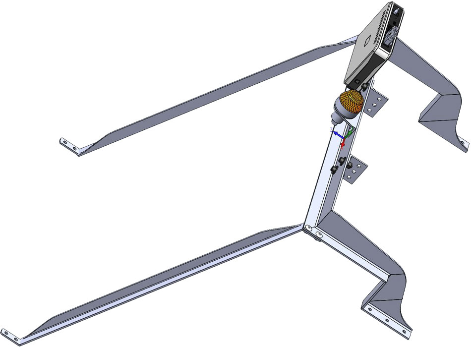
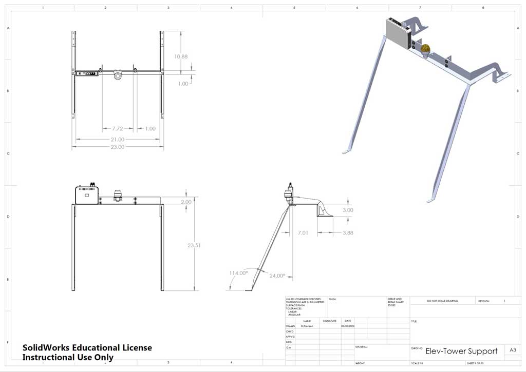
2 Elevator/Tower Upper Support Frame
Upper Frame DWG
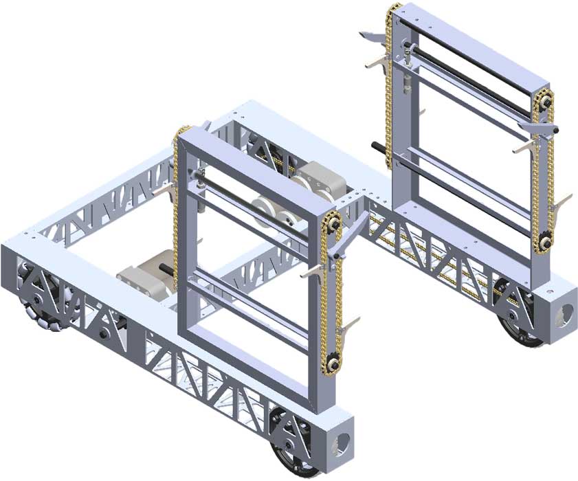
The elevator/tower upper support frame is made up of three parts, the upper cross support between the elevator tote side lifts and the two diagonal angle vertical support pieces. These two pieces further stabilize the elevator upper cross support, which also later will support the two vertical column pieces for the tower slide. These two columns with special sliders allow and support the the recycling container gripper to move up and down, still yet to be created.
Remember to use the related eDrawing file found in your school class folder to see assembly and part details. Manufactured parts used should be in the school networked share CAD folder library. Use folder/file use and naming conventions, name features in feature tree, add the summary information, properties, and material for each custom part made.
Below are the basic steps to complete the elevator/tower upper support frame.
Step to Build
To create this upper support frame, the following steps are to done:
- Create a angle weldment profile: 2.0x1.0x0.125-AL-Au-6061T6.SLDLFP
- Create a 3D sketch to make half of the elevator/tower cross angle support piece, trim and shape, then mirror to finish this cross support piece
- Create the other diagonal angle support piece weldment profile: 0.75x0.75x0.125-AL-Ae-6061T6.SLDLFP to make the diagonal vertical elevator support piece to be used on both sides. You may notice to make this diagonal angle support piece, three new planes were made to align the top and bottom angle fastening ends
- Custom brackets need to be also made from scratch, which could be done by a profile, but in this case, quicker to just make in a sketch - tower support and light brackets
- Once you have all the custom parts made, assemble your elevator/tower upper support frame, add the signal light and wireless bridge devices found in the FIRST kit of parts black tote folder
- Take a close look at the rivet fasteners holding the diagonal supports to cross support, you are to make your own that you can reuse over and over
- Add to your master assembly as a sub-assembly
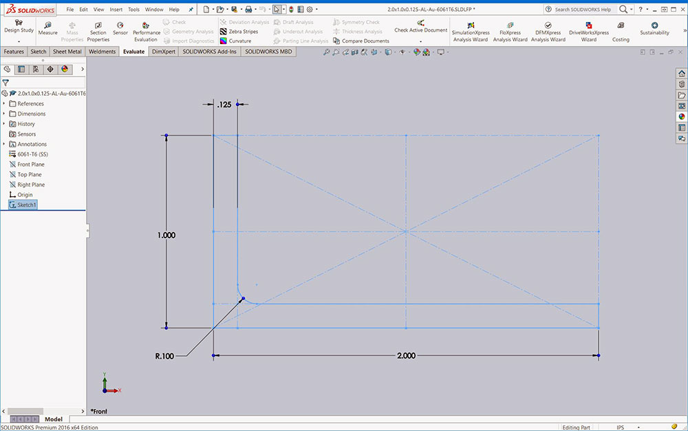
AL profile
AL profile
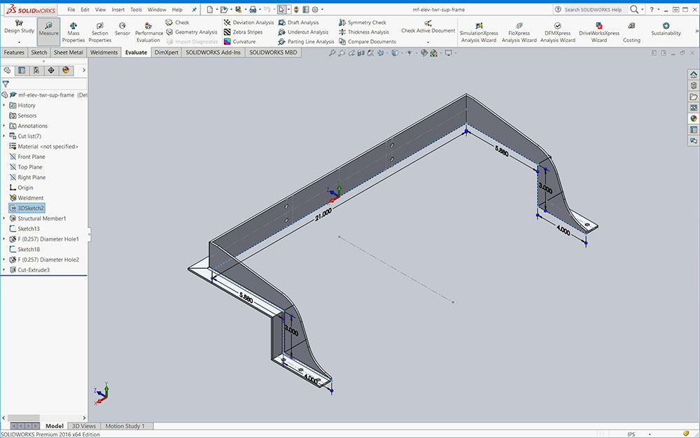
Top frame
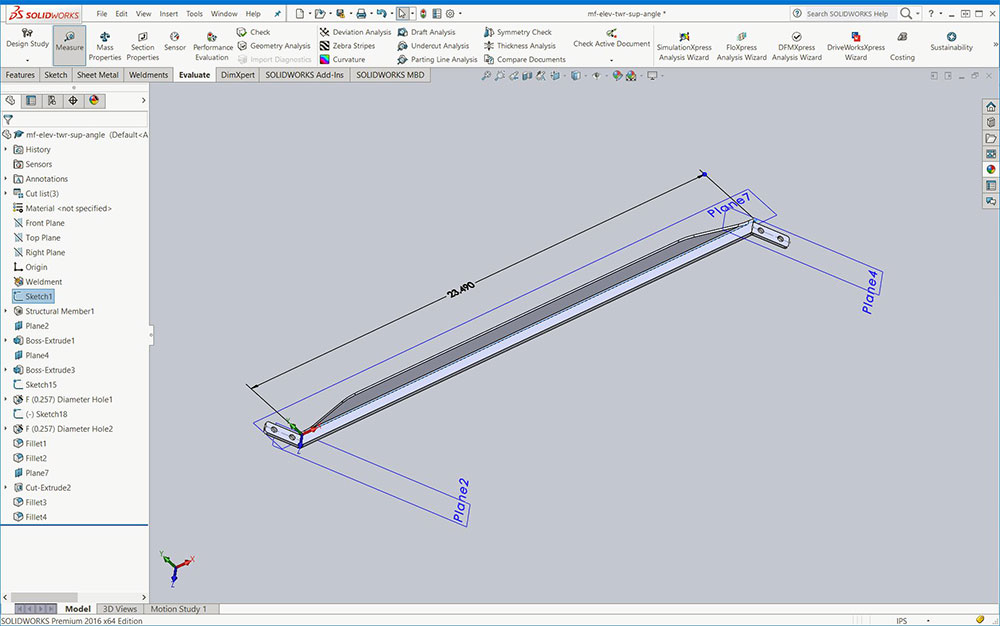
Vertical
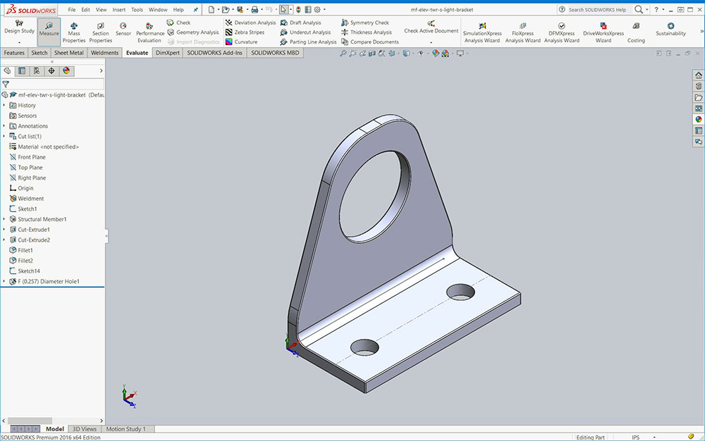
Light bracket
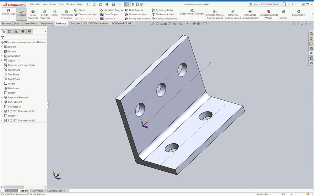
Tower bracket
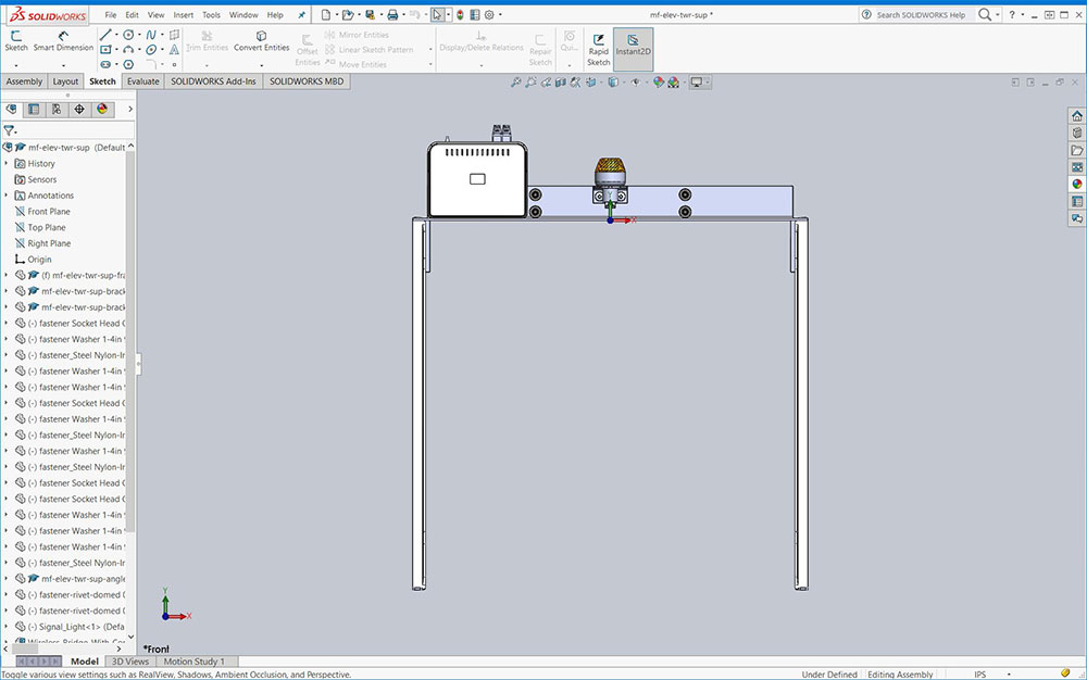
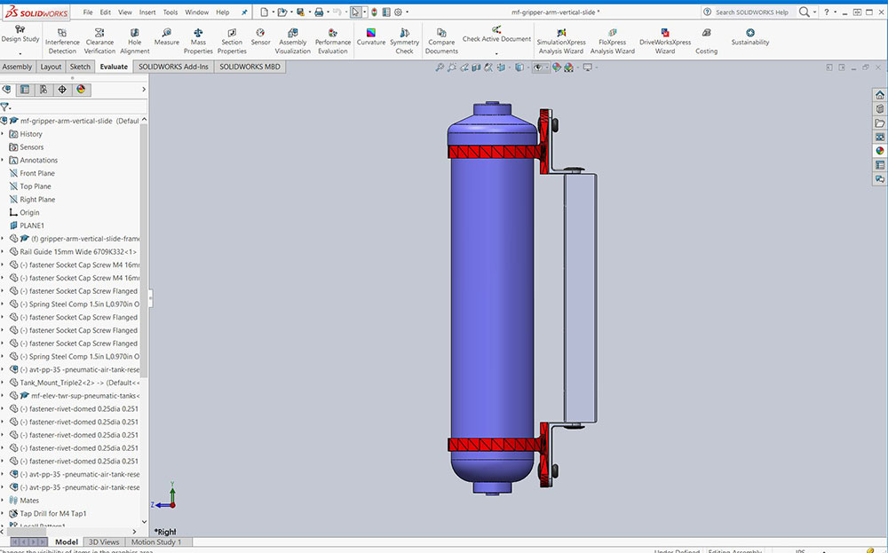
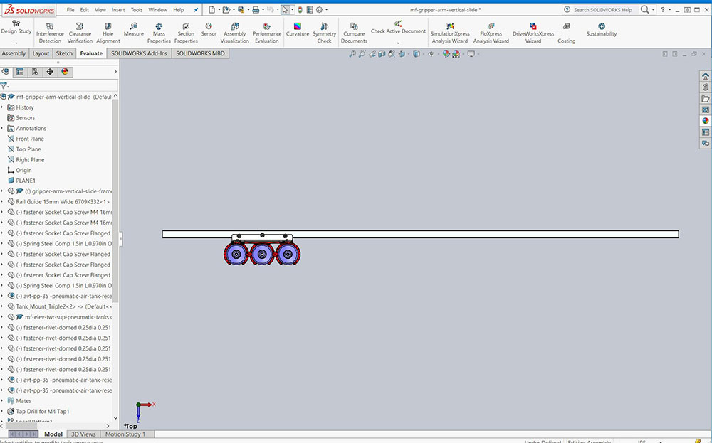
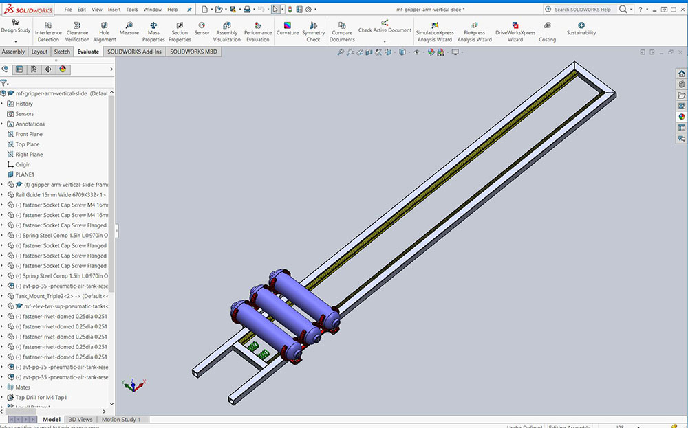
Front view
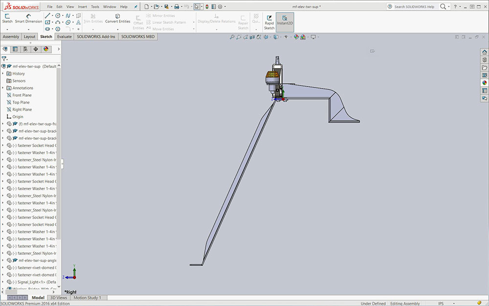
Side view
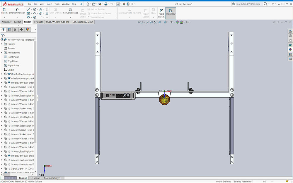
Top view
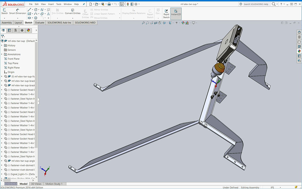
ISO view
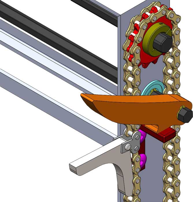
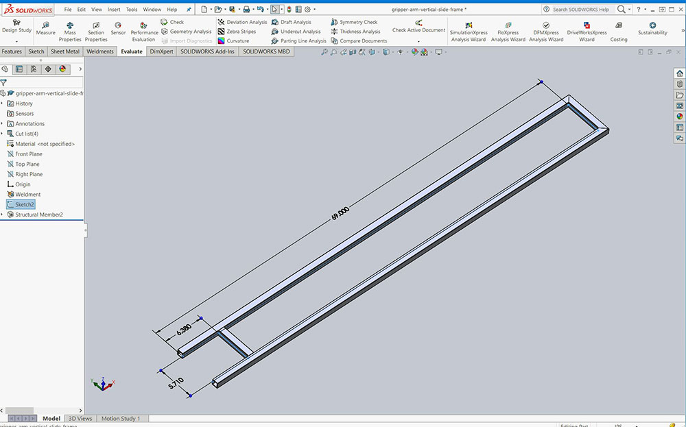
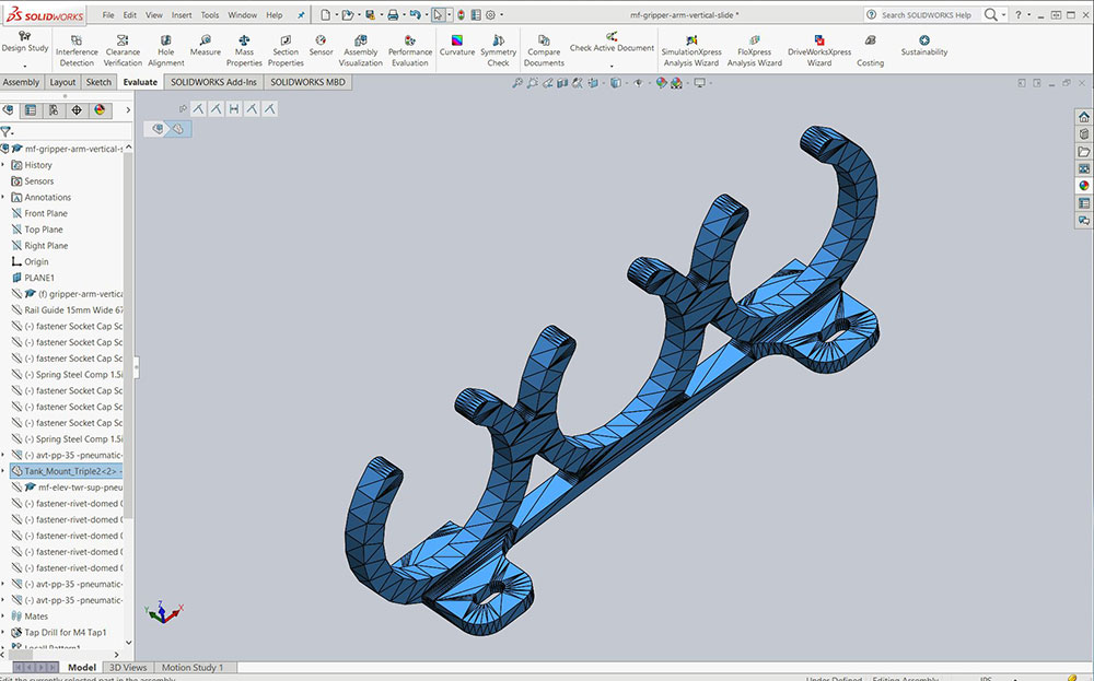
3 Gripper Tower Slide
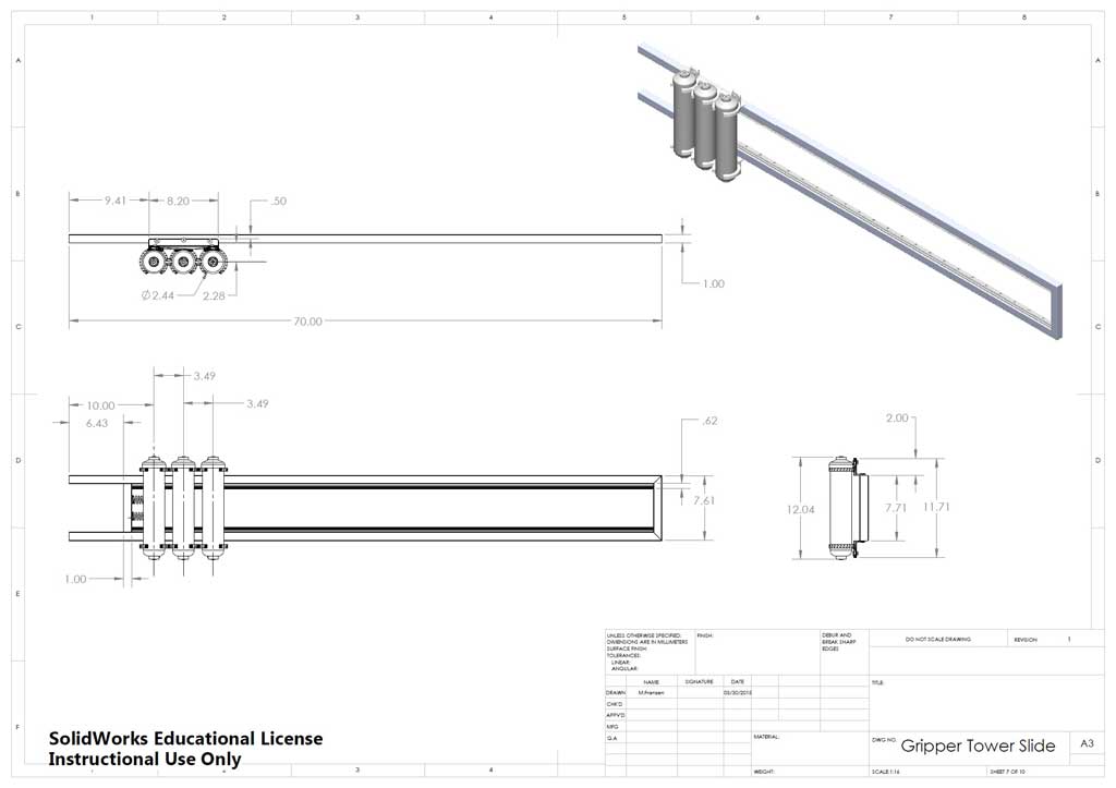
Tower Slide DWG
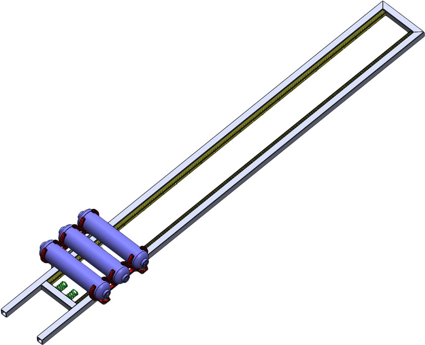
The gripper tower slide in conjunction with the gripper were designed to accommodate collecting six totes with recycling bin on top and also be with-in the maximum height tolerance allowed. The purpose of the gripper tower slide is to allow the gripper to freely travel up/down the track slides. These track slides are mounted to the inside of the two vertical aluminum RHS pieces, to stabilize the 6 totes and recycling container as they are being collected.
Remember to use the related eDrawing file found in your school class folder to see assembly and part details. Manufactured parts used should be in the school networked share CAD folder library. Below are the basic steps to complete the gripper tower slide.
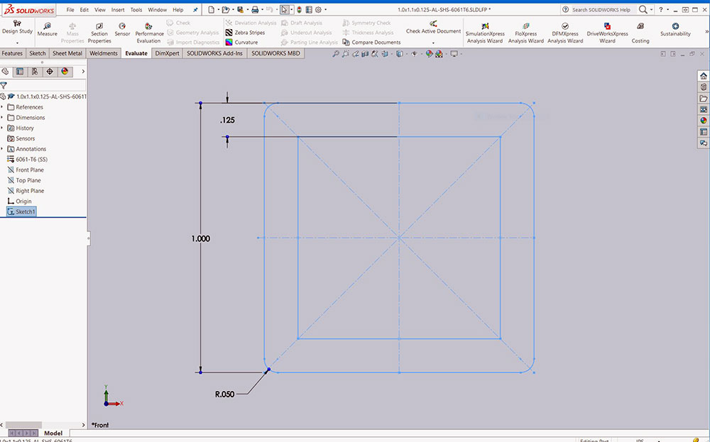
Step to Build
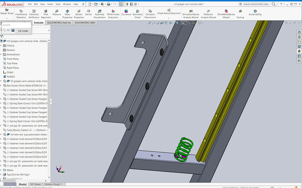
- Create a square hollow section (SHS) profile: 1.0x1.1x0.125-AL-SHS-6061T6.SLDLFP
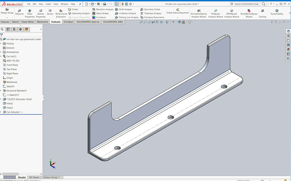
- Using your already made 2.0x1.0x0.125-AL-Au-6061T6.SLDLFP profile, create the pneumatic air tank mount bracket
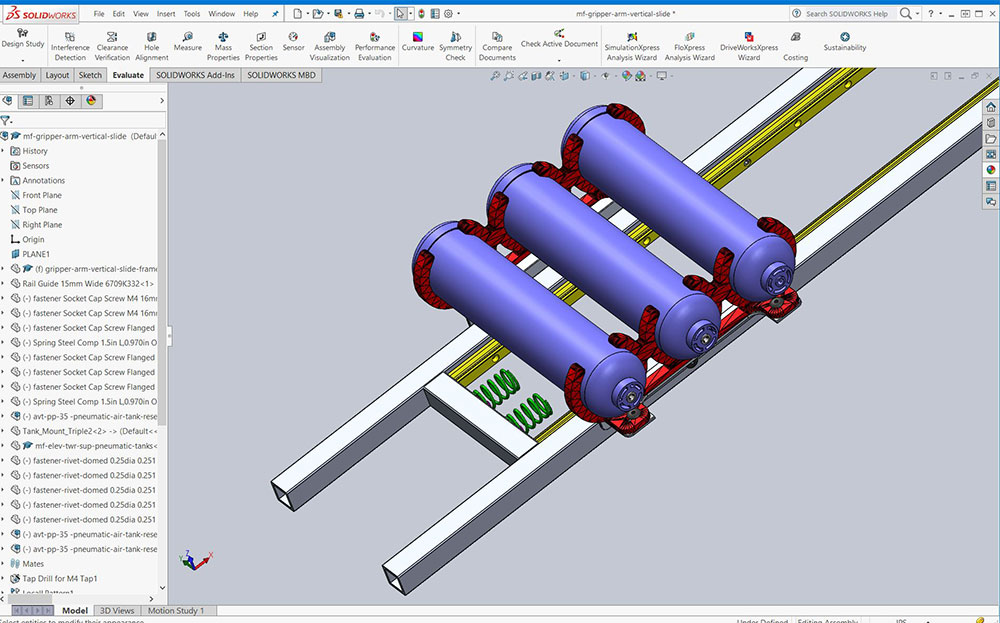
- Create the triple mount pneumatic air tank mount
- Pneumatic air tank reservoirs can be found in the Air tanks should be found in the school class library FIRST robotics toolkit in the MiscellaneousParts folder
- Create compression spring using the variable pitch helix/spiral tool
- Rail guides were from a supplier and will be supplied for you in the school class library
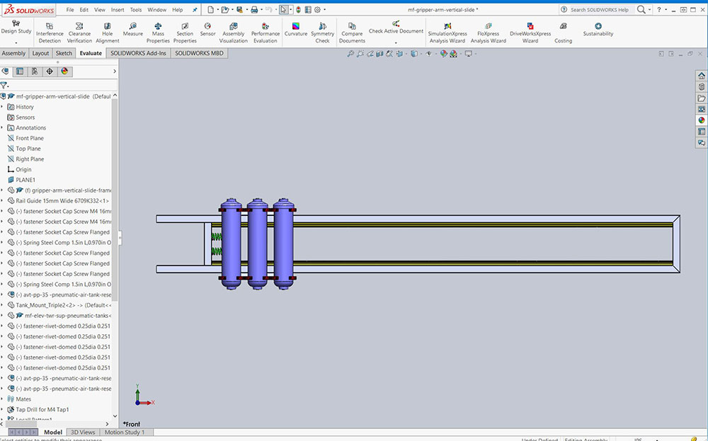
- With all parts ready, assemble the gripper tower slide
- Add tower rail to your master assembly as a sub-assembly
profile
profile
profile
profile
profile
profile
profile
profile
profile
profile
Evaluation:
You are responsible to hand in your sub-assembly as a separate folder for evaluation, master assembly will be looked at in Unit 6.
Make sure your folders, files, organization, and naming conventions are saved correctly, files open up to appropriate views (for example model part and/or assembly - full screen with best ISO view), all CAD files working (double check if you change file/folder names), and include full page JPG images of all CAD work. Remember when you hand in your SolidWorks project, make sure you have completed and handed in the SolidWorks Self/Peer Checklist sheet also. This self/peer evaluation sheet (worth 10% of project mark) is there to help you hand in the best product showing your process build and get written feedback on your completed.

| Evaluation Breakdown Component Descriptions | Marks |
|---|---|
| Always double check that you have completed all components for full marks. | |
| Elevator Mid Frame: Profiles, parts, assembly built | 50 |
| Elevator Upper Frame: Profiles, parts, assembly built | 50 |
| Tower : Profiles, parts, assembly built | 40 |

Unit Conclusion
Now having created the robot frame in the last unit, and in this unit, adding the drive elevator system including lift, mid drive, upper frame support and gripper tower you have had the opportunity to work with more complex assemblies, create more parts, practice working further with folders and file organization, building virtual mechanisms and making more use of Solidworks. Knowing and practicing these skills, steps, and knowledge will further empower your confidence in the design process steps and understanding, being able to communicate more with complex designs, and using Solidworks to create and show those ideas!