Unit 5: Computer Engineering Technology: Interface & Control
This unit will focus on Raspberry Pi, support for student customized projects. Students have already researched and decided on realistic custom projects they wish to build starting from a basic beginner project, intermediate level, and an advanced project. Each higher level incorporates more challenges and components that need to be resolved in their selected design.
Course Units and Descriptions
Use this table for an overview and navigate to each of the course unit pages.
| Unit | Description |
|---|---|
| Review course outline for more details | |
| 1 | Safety & Career - Intro, computers, organization, safety, careers, and custom proposal |
| 2 | Computers & Components - Electronics, operation, design, troubleshooting, and maintenance |
| 3 | Digital Logic & Circuits - Binary, boolean, logic gates, counters/register ccts., calculations, design, & build |
| 4 | Networking & Programming - IP addressing, data routing protocols, services, languages, and concepts |
| 5 | Hardware Interface & Control - Student designed custom project |
| 6 | Showcase & Web Portfolio - Testing and presentation |
Unit Content Activity Quick Links, Click to Jump to Specific Activity!
 Unit 5, Act. 1: Custom Projects

Supplied Materials

Raspberry Pi Poster

Sparkfun Kit
Situation:
Students have a beginner project in mind to use with the Raspberry Pi to learn about human robot interface and control. This will allow students to apply leaning from the rest of the course, and apply new context with a small computer to complete some custom projects.
Problem/Challenge:
Further research (if needed) create, program, test, analyze, and document either a (some sample links) similar beginner circuit project or your preferred own beginner selected project earlier designed or chose. You will work with a supplied Raspberry Pi Model B, revision 2 board and a SparkFun kit full of components all inside a a plastic kit box to keep your all of your projects organized and safe which you will have to familiarize yourself with. Students will work with the GPIO (General purpose input/output) pins along with input/output components programmed with python code to demonstrate their customized projects.
Investigation/Ideas:
Most of your research is already be done and what projects you have decided on, so at this stage it is a matter of jumping in working with your partners, using your own resources already obtained to complete this project. Below are some important points on working with the general purpose input/outputs that students must be aware of for safety of the Raspberry Pi.
First thing to do is familiarize yourself with the components you have to work with from the SparkFun kit. There is a list of experiment projects/tutorials you may want to check out to see what they are using with their kit of parts with their Photon RedBoard. This may give you some additional ideas based on their kit of parts, on what you can do with your Raspberry Pi projects.
GPIO - General Purpose Input/Outputs
One of the Raspberry Pi's great strengths is its ability to interface with the real world through the GPIO pins which you are exploring here. Use care when connecting and handling the Raspberry Pi. Ideally it should have it's own case, so avoid touching component on board as a safety precaution. The 5 volt power pins on the GPIO header can easily be accidently shorted out to one of other pins such as the 3.3V and/or input/outputs, as the Raspberry Pi has no protection in this area. A saftey step you could take to avoid this, is to take a small strip wire insulation and slip over top for protection.
One of it's issues though is when you want to read an analog signal like a temperature or potentiometer, it can't do it. There is a solution though, using a analog to digital converter (ADC) chip will allow you to read those analog signals and use that data in your programming code. Using a basic MCP3008 ADC chip from Digikey is a good opiton
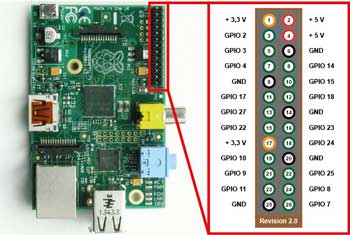 GPIO Pin Layouts

General connection pins for the supplied Raspberry Pi Model B, revision 2 board use a revision 2 pin layout and when programming the RPi, you need to know which pins you can use and how to access them. Sparkfun has a nice page explaining how to get started with coding and set-up basics and suggests using the BOARD physical numbering pin out system (set mode) vs the Broadcom chip-specific pin number system(BCM), when wring directly to the pin headers. Pinout site has a great interactive click and see what each pin is about and if you have only the 26 pin layout, just ignore the extra ones. You can download a image to print on paper, cut out and push onto your pin header (use rev 2) which shows all your connections.
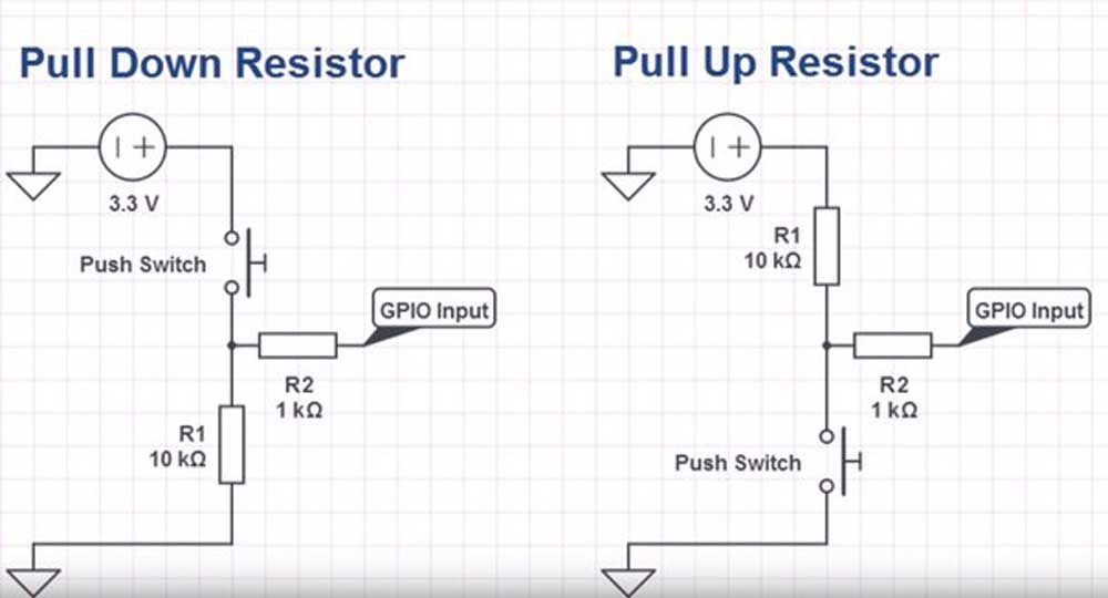
Push Button Inputs
Connecting inputs such as momentary push buttons requires more than just a push button. When a GPIO pin is set as an input, is said to be "floating" and does not have a defined voltage level, which is what you need to set a high or low signal. To resolve this you can either use a Pull up or Pull down resistor. For example a Pull down would have one side of the momentary push button normally open connected to the 3.3 V and the other to 10K Ω resistor to the ground and a 1 K in series (for safety against shorts) to the input pin, giving it low current path to ground and low signal. When the button is pressed there is a lower resistance path to the output pin, there-by creating a reliable high signal. It is possible to also enable an internal resistor by using an internal Pull down command with the GPIO.setup() function. Another in depth explanation has some great related resources also. Including a slight time delay can prevent button debounce or false inputs. Make sure you check your push button for the correct connections to use, by doing a continuity test with a multi-meter to ensure you are connecting your push button switch properly.
GPIO Current Limitations
When working with the GPIO pins, take care in understanding the output current limitations. First understand and insure devices connected to the output pins is not exceeding their limits. Generally 3mA is a consideration, but a maximum of 16mA per pin is possible with total current draw from all pins not exceeding 51mA. There is a registry that allows you to set the drive strength of all of the pins from 2mA to 16mA, meaning keeping up current draw while maintaining voltage levels for logic inputs. More about this and how output impedance will affect voltage input levels in Understanding the outputs. Bottom line, surpassing safe current level draws will slowly or quickly, deepening on amount, will burn out the unit. If you need more current capacity, you can get axillary boards with their own power supply and be able to connect higher load/current demanding current devices.
Resource Links
Related Project Components:
- Raspberrypi.org
- PCB Versions
- Wikipedia
- Lazarus on RPi
- MUO Blogs
 Setting Up, 9.09
- RPi Tutorials
- Intro to GPIO, 17.47
- Python sketches
- GPIO Inputs, 18.40
- GPIO Control, 15.38
- GPIO & Python PL 9
- Pi GPIO Tutorial, 8.56
- LED To Raspberry Pi, 6.18
- Push switch with Pi, 5.40
- LED with your Pi and Python
- Pi GPIO pins and Python
- Sparkfun Raspberry GPIO
- Breadboard how-to
- Sparkfun Micro OLED
- Physical with Python
Related Project Ideas:
- RPi Projects
- Make
- PingBin
- DIY Maker Pro
- Open Electronics
- ACC RPi
- elinux
- Adafruit
- GitHub
- Instructables
- Gen Search
- Security Camera
- Makeuseof.com
- Pi Push Notifications
- Washroom alert, 8.14
- Home Theater, 8.15
- Amazing Gadgets, 13.44
- Auto Lighting, 2.29
- Fav RPi Projects. PL
- Top Rpi projects 2014
- Analog Graphing
- Data in Graph, 8.41
- Plotting Data with Python
- Plotting Data
- Data to COSM
Support Operation:
- GitHub Pi Repository
- Gordons Projects
- Starting Pi
 GPIO cheat sheet
- Pi GPIO Pinout
- Python on a MC - 240kB
- GitHub Pi Repository
- Wikipedia Pi
- The Thingbox
- RPi Site
- GPIO Zero
- PIC Programmer
- Understanding the outputs
- Pi GPIO Explained
Local suppliers:
On-line suppliers:
Create/Construct:

The following are some general points to keep in mind when working on your project. Time should also be a factor here, so be aware that the bulk of your time for this unit is to be focused on your final custom project, so plan on about one to two days on the beginner basic GPIO project, the use the rest of your time for your intermediate and/or advanced final custom project.
You should also keep in mind the SPICE design process which we have looked at in the past and use that to support your project work process and documentation (pictures tables, charts and fritzing). Remember to use proper coding conventions and commenting similiar to your Python Action progrmaing project. Here are some general steps to follow in completing your final custom project:

Raspberry Pi push button/LED project
- With your Raspberry Pi Model B, revision 2 board and a the SparkFun kit complete the Part Descriptions Research and Hardware Parts Check sheet
- If you need to further review or check out more info on set-up or related resources with the Raspberry Pi, click here
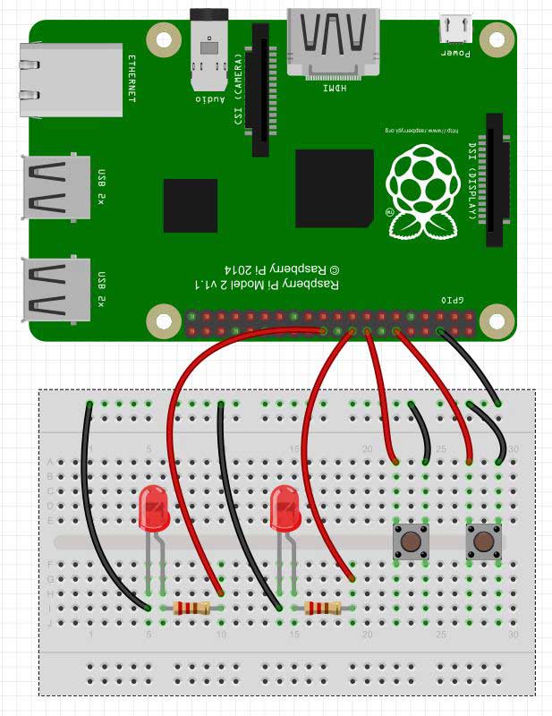
- Complete your beginner project earlier reasearched (which was to include low number of common inputs/outputs, minimal programing, and little if not any networking). If your project is not appropriate or timely try the sample 2pb-2led.py or sample 2pb-dimmer project connected up with some additional variations (view hardware connections) to demonstarate and showcase in your custom projects folder
- Decide and start on your final custom project, your previously researched intermediate or advanced custom project, and start organizing representative hardware components to allow you to design and write your Python code for use with the Raspberry Pi, GPIO's, networking, prototyping breadboard, hardware, etc.
- Remember to document (text and pictures) your steps and learning in detail on your wiki custom projects area
- Informal class demonstration and custom project documentation log is to done to show completed work and learning achieved.

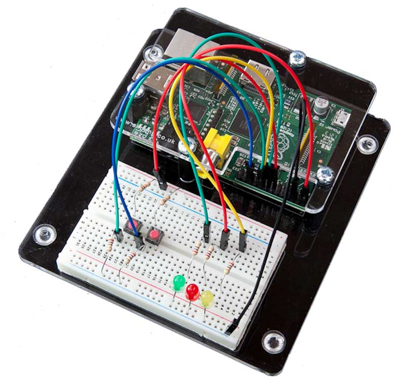
Raspberry Pi sample set-up from step 2
Note one of your three portfolio entries could be showcasing your final custom programming and interfacing with your Raspberry Pi.
Evaluation:
The following is a breakdown of marks for the part definitions, part check, your basic level custom project demo/ wiki report , along with your final customized intermediate/advanced project/wiki report.

| Evaluation Breakdown Component Descriptions | Marks |
|---|---|
| Always double check that you have completed all components for full marks. | Part Definitions - Fill in what each of the parts are and their function | --- |
| Hardware Part Check - Identify and check-off all your parts in your kit | --- |
| Custom Basic Project - Demonstration and explanation of operation | 20 |
| Wiki Report - Wiki project steps, programming, and resources | 15 |
| Custom Intermediate/Advanced Project - Demo & operation | 60 |
| Wiki Report - Wiki project steps, programming, and resources | 40 |