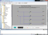
Unit 3: Computer Technology - Electrical and Digital Circuits
This unit will introduce you to basic circuit theory, types, calculations, design, troubleshooting, and logic gates.
Course Units and Descriptions
Use this table for an overview and navigate to each of the course unit pages.
| Unit | Description |
|---|---|
| Review course outline for more details | |
| 1 | Careers & Safety- Intro, computers, organization, safety, and research careers |
| 2 | Computers- organization, hardware, design, software, maintenance, building, repair, and troubleshooting |
| 3 | Circuits- Electrical characteristics, calculations, components, digital logic design, project build, and troubleshooting |
| 4 | Tetrix-Bot- micro controllers, electronics, robot builds, circuit building, programming, robot navigation, testing, and troubleshooting |
| 5 | Web Portfolio- Showcase course work, projects, and understanding with web portfolio and presentation |

Unit Content Activity Quick Links, Click to Jump to Specific Activity!
- Unit 3, Act. 1: Circuit Types and Calculations
- Cct Theory, Circuits: Series, Parallel, Units of Measure, Complex, Eval
- Unit 3, Act. 2: Electrical and Digital Logic Gate Circuits
- Background, Circut Design, Operation, LogoSoft, (Steps) Equivlant, Stop-Start, For-Rev, Eval
- Unit 3, Act. 3: Automated Door Logic Gate Circuit Design
 Unit 3, Act. 1: Circuit Types and Calculations
Situation:
Computers and robots have one thing in common, circuits. Circuits are what drive all of our technology. More importantly electricity is what runs on those circuits making everything work. This is a very simple concept to understand, but in order to work with this kind of technology, such as troubleshooting a circuit problem, a closer look at circuits and how electricity interacts is important to know and understand. Because electricity can not be seen, and is dangerous to come in contact with, using measuring tools tools and some theory, we can diagnose and understand what is happening in a circuit.
![]() This will allow you to not only understand, design, and build circuits, but also troubleshoot and fix circuits problems.
This will allow you to not only understand, design, and build circuits, but also troubleshoot and fix circuits problems.
Problem/Challenge:
Review the characteristics of electricity and how it flows in circuits (Circuit Theory Presentation). Specifically electron flow, ohm's law , and power in series, parallel and complex ccts. You will complete 2 worksheets on the series, parallel, and complex circuits, showing all formulas, steps, and answers.
Investigation/Ideas:
 Circuit Theory Presentation
Before starting on these circuits we will need to look at ![]() Circuit Theory on the following areas:
Circuit Theory on the following areas:
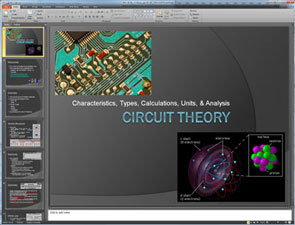 Atomic structure of related materials
- Electricity and electron flow
- Ohms law
- Power
- Circuit Types
- Series
- Parallel
- Combination
- Quantities and units of measure

Resource Links
All About Circuits site is an excellent site to learn all about electrical related information. It has e-book sections, worksheets, videos, and a forum. We will be referring to this site for several future project related tasks. Currently you will find all that is in the above presentation, in more detail here on this site.
 Create/Construct:
For the following two types of circuits, you will need to apply ohms law and power formulas to find the circuit unknowns.
Series Circuit Introduction
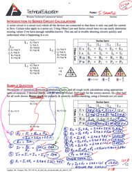
- Start with the Series Intro sheet handout and copy the calculation answer format down with pencil. The image to the left can be enlarged to see it up close. Pay close attention to the steps and how the circuit was completed. Note all work must be shown when doing these calculations to get full marks, as fifty percent of the mark goes towards showing the process i.e. your steps in how you calculated your answers.
- Next you will work on a new
 Series Cct 1 sheet handout to calculate all unknowns using ohms law, the series cct laws, and Power to find all values. Follow the same method as was shown in the series cct sample assignment you just copied down above. Once you have calculated all values, you are to complete a double check calculation, which will prove that your answers are correct.
 Parallel Circuit Introduction
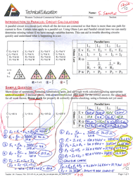
- Start with the Parallel Intro Sample sheet handout and copy the calculation answer format down with pencil. The image to the left can be enlarged to see it up close. Pay close attention to the steps and how the circuit was completed. Note all work must be shown when doing these calculations to get full marks, as fifty percent of the mark goes towards showing the process i.e. your steps in how you calculated your answers.
- Next you will work on a new
 Parallel Cct 1 sheet handout to calculate all unknowns using ohms law, the series cct laws, and Power to find all values. Follow the same method as was shown in the series cct sample assignment you just copied down above. Once you have calculated all values, you are to complete a double check calculation, which will prove that your answers are correct.
 Series and Parallel Circuit Calculations with Units of Measure
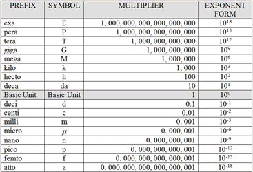
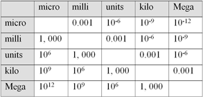
The above circuit samples and accompanying calculation handouts were designed with simple easy numbers so you could focus on the process. It is very rare that electrical circuits have easy numbers to work with. In fact a lot of time in electronics, some numbers you work with will be either be very big or very small and that is where units of measure come in. As reviewed in the above Circuit Theory Power Point presentation, and the next handouts includes this, so you will need to apply ![]() Units of Measure rules when numbers are either really big or small.
Units of Measure rules when numbers are either really big or small.
![]() Remember, when working with different units of measure, that those numbers in a formula calculation must be all the same when making those calculations.
Remember, when working with different units of measure, that those numbers in a formula calculation must be all the same when making those calculations.
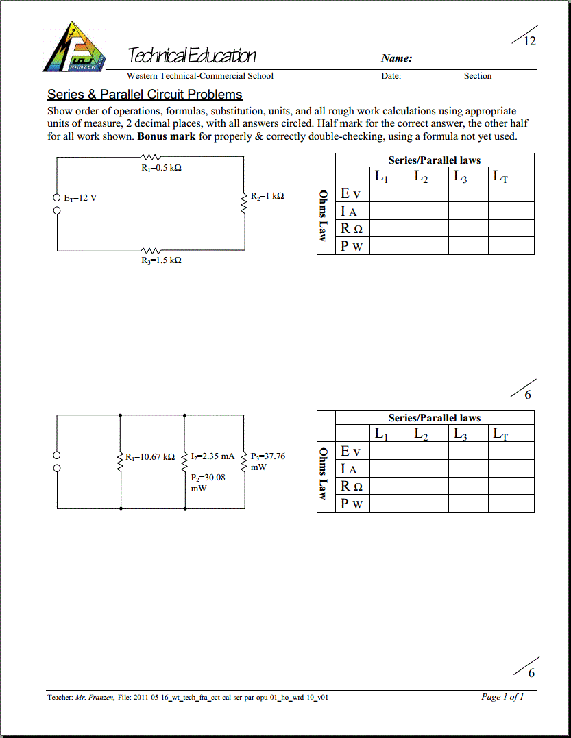
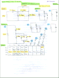
Find all the unknowns in the following handout as seen above: ![]() Series, Parallel, and Units of Measure Circuit Problem Handout 1, Handout 2 following the same sample process that was shown earlier and the units of measure support charts given:
Series, Parallel, and Units of Measure Circuit Problem Handout 1, Handout 2 following the same sample process that was shown earlier and the units of measure support charts given:
 Complex Series/Parallel Circuit Analysis and Calculations
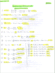
- Referring to the above Circuit Theory Power Point presentation, you can follow the complex circuit breakdown analysis. For the sample to the left, note how the circuit drawing is simplified each step from a to e. These steps are explained in detail here if you wish to review it one more time. Your first assignment
 Complex Series/Parallel Analysis Variable will be to analyze and simplify the circuit without calculations. Simplify and redraw the circuit however many times you need to get a final complex statement using letter variables
 - Your next assignment
 Complex Series/Parallel Analysis and Calculations you will do the same except this time actually calculate all the unknowns using calculations, circuit diagram simplification and circuit analysis.
 Evaluation:
Each circuit assignment problem must show all work, to get full marks and once taken up in class, 50% of the lost marks can be reclaimed that day, by showing the corrections completed on a separate area with a different coloured pen with a title above stating "Corrections @ 50%".

| Evaluation Breakdown Component Descriptions For Presentation | Marks |
|---|---|
| Always double check that you have completed all components for full marks. | |
| Series Intro Sample - copied neatly in pencil showing all formulas and calculations | 10 |
| Parallel Intro Sample - copied neatly in pencil showing all formulas and calculations | 10 |
| Series Ccts 1 - Order of operation, all formulas, and calculations | 12 |
| Parallel Ccts 1 - Order of operation, all formulas, and calculations | 12 |
| Series/Parallel Ccts 1 - Order of operation, units of measure, formulas, & calculations | 24 |
| Complex Series/Parallel Analysis Variable -cct diagram simplification and final variable | 15 |
| Complex Series/Parallel Analysis and Cal. - diagram simplification and all unknowns | 25 |
 Unit 3, Act. 2: Electrical and Digital Logic Gate Circuits

Situation:
Understanding about electricity, circuit characteristics, and how electricity flows through circuits is important in circuit design. Circuit design process steps allow you to logically develop circuits based on your requirements. Learning how to draw and communicate your circuit ideas is very useful in related engineering fields. All circuits depend on three components namely a power a source or supply, a control or function, and a intended result, or output. As discussed earlier, electrical circuits are used in almost everything we do with our lives. More directly, a lot of it is electronic. Electronics is designed a lot with Digital Logic Circuits.
![]() Being able to use digital logic with circuits allows us to design and understand the control that is found in everything we use that has electronics. Knowing this we can create our own electronic circuit control systems.
Being able to use digital logic with circuits allows us to design and understand the control that is found in everything we use that has electronics. Knowing this we can create our own electronic circuit control systems.
Problem/Challenge:
Familiarize yourself with the different logic gates, their names, symbols, notations, truth tables, and mechanical equivalent circuits by completing a chart. Also on the back you will fill in the steps you would take to design a circuit.
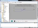
Using Siemens LOGO! Soft Comfort software with digital logic, build a circuit that will work similar to a standard stop-start motor control circuit. Once you have this done, you will be familiar with the program operation and the latch mechanism you used, in order to also create a similar motor control circuit, Forward/Reverse Motor Control Circuit.
Both circuits must have a centred header with a title, name, and detailed description of the circuit requirements and operation, and include the three major sections of the circuit sub-titled: Inputs, Functions, and Outputs. Circuits are to be handed in both a LOGO!Soft Comfort Drawing file .lsc and a exported .jpg
Investigation/Ideas:
 Background
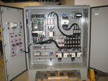
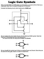
An in-class discussion on different circuit types: hardware/mechanical, electronic, and digital logic will set the stage as to why we are looking into digital logic. Below show different types of circuits and it is important to know the differences, purpose, use, and future prospects.
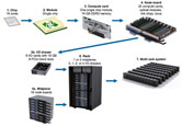
Super Computers
 Circuit Design Presentation
Start by reviewing key information on the following ![]() Circuit Design presentation which covers the following areas:
Circuit Design presentation which covers the following areas:
- Circuit Design Process
- Electrical Symbols
- Ladder Diagrams
- Latching Circuit Design
- Digital Logic
- Basic Logic Gates
- Sample Circuit Problem
- Digital Logic Circuit Problem Tips
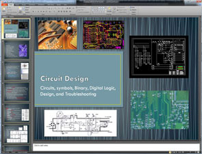
After reviewing this presentation, you will have a better understanding on electrical circuit components, symbols, and ladder schematic diagrams. It will then go into digital logic gates and compare equivalent electrical circuits, and finally review steps to create a digital logic gate cct.

Resource Links
Circuit Operation
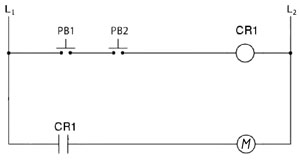
Looking at a standard mechanical electrical circuit, components, and it's operation is important to know and understand so that you can create the equivalent digital logic circuit. The above circuit has two normally open push buttons that need to be both pushed in order to energize CR1 (control relay 1) which in turn will change the state of the contact on the next rung turning the output M (motor) on. As all electronic computer circuits are based on digital logic circuit design, lets see if we can convert this circuit to a digital logic circuit.
 LogoSoft Virtual Simulation Software
You will need to familiarize yourself with the LOGO! Soft Comfort software program through the use of the program it's self and the help section. Below are some links to download this free application. Use the first link for a Win64bit small exe install file. If you are on another system, use the third link which has all system installs:
- LogoSoft Comfort Demo 8 - Win64 setup.exe
- LOGO! Soft Comfort software (Sign-in/register req.)
- logo_soft_comfort_v8_demo- all ver (1.52 GB zipped file)
Specific things to review in this program are the following:
- User Interface
- Standard Tool bar Tools
- Simulation Tool bar Tools
- I Standard push button inputs
- AND Function
- Q Standard outputs
By first looking at basic hardware mechanical/electrical circuits, and then converting them to digital logic circuits will help you understand circuit theory design from both aspects. A deeper understanding of both types of circuits will allow you to design more complex circuit designs that have many requirements.
 Create/Construct:
Below are your ![]() project work assignment steps based on the required Problem/Challenge as stated above. Each section is to be completed in the order as directed below:
project work assignment steps based on the required Problem/Challenge as stated above. Each section is to be completed in the order as directed below:
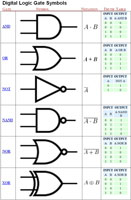
A) Logic Gates & Equivalent Mechanical Circuits
- Fill out the
 6 main logic gates, their notation, truth table, and their mechanical circuit equivalent. You may use the
  Circuit Design presentation for support with the mechanical circuit equilvents that you will need to draw in the last column. This can also be done on a blank sheet of paper with about 2" per row, and 5 columns to organize and fit the required information. The following are the 5 colum titles:
- Gate Name
- Symbol
- Notation /Operator
- Truth Table
- Mechanical Cct Equivalent
- Divide the back of the page into three equal spaces for the following: Title: Circuit Design Steps, then neatly name and describe in 5 major steps to design and create a working circuit design using the SPICE model and circuit design goals (5 marks)
- Title: Stop/Start Motor Control Electrical Ladder Schematic Cct and neatly sketch out (copy) the Stop/Start motor control schematic (not power cct) with the proper symbols carefully drawn out and labeled, while noting the latching safety cct design (5 marks)
- Title: Stop/Start Motor Control Digital Logic Cct and neatly design a working logic control circuit that operates with the same control function as the electrical cct above. Control/input on the left, functions in the centre, and output on the right using appropriate labeled symbols and wire connections to show a working stop/start cct with the latching safety design implemented (10 marks)
- Hand in for evaluation.
 B) Stop Start Motor Circuit
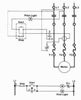
- Draw a neat circuit ladder diagram of a stop, start motor control circuit similar to the one in the Circuit Design presentation slide that talks about latching circuits
- Ensure that the symbols are correctly drawn neatly using the full width of the page in portrait format
- Have the teacher check to see that your drawing is correct
- Below draw the equivalent circuit using the logic gates: AND, OR, and NOT
- When the digital circuit solution is complete
- Using LOGO!Soft open up a new file and name it appropriately with your Last initial, first name, - project name
- Insert title, name, given information, and Sub titles for Inputs, Functions, and outputs using the text tool (Tip: See sample in presentation)
- Insert your Inputs, Outputs, and Functions using the full screen, configuring each as needed including switching options, comments, etc.
- Connect up wiring ensuring it is neat and objects are organized and aligned
- Simulate and test to see if circuit is working the way it is required
- Save, and have teacher check your work for marks, and hand-in both the .lsc and an exported .jpg file
 C) Forward/Reverse Motor Circuit
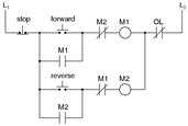
- Using the following circuit diagram given, create the digital logic equivalent using any of the basic logic gates that were reviewed in the presentation
- Remember to setup your page correctly, place components in the appropriate locations and minimize wire crossings
- Once you have a finished and circuit is working correctly have the teacher check it and hand-in both the .lsc and an exported .jpg file
 Evaluation:
Each circuit must have a centred header with a title, name, and detailed description of the circuit requirements and operation, and include the three major sections of the circuit sub-titled: Inputs, Functions, and Outputs. Circuits are to be handed in both a LOGO!Soft Comfort Drawing file .lsc and an exported .jpg

| Evaluation Breakdown Component Descriptions For Presentation | Marks |
|---|---|
| Always double check that you have completed all components for full marks. | |
| Logic Gates and Cct Design Steps - Names, symbols, notation, truth table, cct equivalents | 15 |
| Circuit Design - Describe SPICE process steps for circuit design | 10 |
| Stop-Start Motor Cct - mechanical and digital circuit designs on Logo Soft | 20 |
| Forward-Reverse Motor Cct - Logo Soft layout, neatness, and cct complete | 30 |
 Unit 3, Act. 3: Automated Door Logic Gate Circuit Design
Situation:
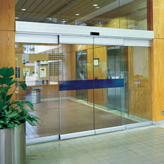
Creating simple logic circuits from previous mechanical electrical circuits has helped you not only understand how digital logic gates work, but also helped you understand a little more about circuit design. With real world situations, you will find a multitude of electronic circuits needed to accomplish a goal with a whole number of requirements, restrictions in a safe manner.
![]() Being able to design, communicate, and build real life situation circuits will allow you to also work with things such as the boe-bot, a future project we will be working with.
Being able to design, communicate, and build real life situation circuits will allow you to also work with things such as the boe-bot, a future project we will be working with.
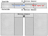
 Problem/Challenge:
Using Siemens LOGO! Soft Comfort software, build digital circuit for a automatic door system similar to what you would find at your local big box supermarket. You are to try and build it with as few digital logic gates as possible and operate as follows:
Table of Inputs and Outputs and their Functions
| Inputs & Outputs | Function |
|---|---|
| I1 | Motion Sensor Inside |
| I2 | Motion Sensor Outside |
| I3 | Closed Limit Switch |
| I4; | Open Limit Switch |
| Q1 | Open Motor |
| Q2 | Close Motor |
General Door Operation:
When a person approaches the automatic door, either the inside and/or outside sensor will open the doors. Once doors are open and open limit switch changes state, 4 seconds must past before the door starts to close. If a person steps into range of inside/outside sensors, door will stay open until 4 seconds after they are gone out of range. Once 4 seconds times out with no one around, door will close. If one of the motion sensors picks up movement, the door must immediately stop closing and open up again and hold open again for an additional 4 seconds , then attempt to close again. When closed, the closed limit switch will change state, and close motor will stop. Automatic door waits until next person.
 Investigation/Ideas:
Using the previous circuits in the last activity, you learned about latching circuits. This concept can be used with this circuit also. You will need to also add a timer in this circuit design. There are two types of timers, on delay and off delay. You will need to experiment with both to see which one will work best for your circuit.
Key Points to Keep in Mind
- When somebody approaches, the door must open automatically
- Once the open cycle has been engaged, the door must fully open
- The door must remain open until there is nobody in the doorway for 4 seconds
- If there is nobody in the doorway anymore (no motion detected) and the door has completed it's open cycle, then after 4 seconds the door should begin to close
- The open limit switch activates (goes high) when the door is fully open
- The close limit switch activates (goes high) when the door is completely shut
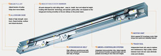
Here are a couple of door drive motor systems you can take a look at a little closer:
 Resource Links
Timers
For more details on these
4 different timers, open up
the help file in the LogoSoft
Comfort program,
Interested in more in-depth information on sliding doors, the following links have some good information in detail:
- Ingersoll Rand Door Company
 Sliding Door Drive Manual
- Sliding Door Design Guide
- Stanley Slide Door Systems
![]() You may also want to check out other relays such as the latching relay, as it may save you some unnecessary functions
You may also want to check out other relays such as the latching relay, as it may save you some unnecessary functions
 Create/Construct:
Below are suggested steps you can take to design and create the required digital logic circuit.
- Clarify in your head what a logic gate does and review the 5 basic gates (NOT, AND, OR, NAND, NOR, XOR)
- Review our solution to the Start/Stop & Forward/Reverse Problem
- Use the Siemens LOGO!Soft Comfort software to create/design/construct a solution for the Open Motor circuit, being careful to utilizing output Q1 for the Open Motor, I1 for the Inside Motion Sensor, I2 for the Outside Motion Sensor, and I4 for the Open Limit Switch
- Thoroughly test this circuit and be sure that it works properly be sure that it works properly
- Then work on a solution for the Close Motor circuit, being careful to utilize output Q2 for the Close Motor, the same I1 (as the previous circuit) for the Inside Motion Sensor, the same I2 for the Inside Motion Sensor, I3 for the Close Limit Switch, and the same I4 for the open limit switch
- Before you can complete the above step you will need to investigate the operation of the Special Function On-Delay and Off-Delay Timers
- Once you have a working circuit ensure that you have included a title, a general description, sub titles- Inputs, Functions, and Outputs, your name, and clean up wiring and component locations, then have the teacher check it
 Evaluation:
Each circuit must have a centred header with a title, name, and detailed description of the circuit requirements and operation, and include the three major sections of the circuit sub-titled: Inputs, Functions, and Outputs. Circuits are to be handed in both a LOGO!Soft Comfort Drawing file .LSC and an exported .PDF

| Evaluation Breakdown Component Descriptions | Marks |
|---|---|
| Always double check that you have completed all components for full marks. | |
| Open Cycle - Once activated, can not be interrupted by loss of motion input | 5 |
| Open Door Timer - Completely open with no motion for 4 seconds prior to door closing | 10 |
| Close Cycle Safety - If either motion sensor is activated, doors immediately stops and opens | 10 |
| Number of functions- not including I's and Q's, less results in a better mark (6 to +10) | 5 |
| Final Circuit Design - Organized, neat, labeled, and working | 10 |
