Unit 6: Grade 10 Technological Design - Robotics - Assemblies
Making complex components such as a robot will be made up of several model parts. This unit will introduce you to how this is done. Assemblies are made up of not just model parts, but can also include sub assemblies. This means that you can add parts to make a small assembly, then use that assembly in a larger "parent" assembly. This allows the designer to focus on sections or areas of the whole project. Think of something large scale such as a jet airplane. Engineers could have the jet engine as an assembly made up of sub assemblies and parts that can be later brought into a master assembly to show the full completed jet with the fuselage and jet engine fit together. This can be very beneficial to different engineering teams that may be in different companies and/or countries.
Course Units and Descriptions
Use this table for an overview and navigate to each of the course unit pages.
| Unit | Description |
|---|---|
| Review course outline for more details | |
| 1 | Careers & Safety- Intro, computers, organization, and careers |
| 2 | Technical Sketching- freehand sketching, ortho, dimensions, ISO views, custom ortho design |
| 3 | Basic 2D & 3D CAD Intro- 2D coordinates, lines, ortho views, 3D drawing, and custom design digitized |
| 4 | 3D Parametric Design- 2D sketch, 3D parts, feature tools, drawings, exporting for 3D printing |
| 5 | Sheet metal Design- thin material design, folds, assemblies, 2D print, project design, testing, and build |
| 6 | Robot Assembly- part reproduction, part assemblies, custom function design and build |
| 7 | Web Portfolio- Showcase course work, projects, and understanding with web portfolio and presentation |
Unit Content Activity Quick Links, Click to Jump to Specific Activity!

 Unit 6, Act. 1: Introduction to Assemblies

Situation:
Being able to make solid and sheet metal parts has been learned and the next step is to learn how to create larger and more complex projects using tools commonly found in todays 3D CAD programs. It is time to think on a larger scale by not just making a part, but a mechanism, or a component with multiple parts making up a final product.
Problem/Challenge:
This activity challenge is to use the ![]() Magnetic Block tutorial to learn about not just assemblies, but also how to add welds to your assembly, adjust colour appearance of parts, and make use of the SolidWorks library of parts that is included with the application. Once the magnetic block model is complete, create a drawing showing your assembly, and additional sheets to show individual parts in usual orthographic/isometric format. On completion, you will digitize a boe-bot into 3D showing the main components and detail as time permits to not only familiarize yourself with the components but also practice and demonstrate your drawing skills. Drawings to include an assembly, sheet metal frame, electronic board, servo motor, and wheels.
Magnetic Block tutorial to learn about not just assemblies, but also how to add welds to your assembly, adjust colour appearance of parts, and make use of the SolidWorks library of parts that is included with the application. Once the magnetic block model is complete, create a drawing showing your assembly, and additional sheets to show individual parts in usual orthographic/isometric format. On completion, you will digitize a boe-bot into 3D showing the main components and detail as time permits to not only familiarize yourself with the components but also practice and demonstrate your drawing skills. Drawings to include an assembly, sheet metal frame, electronic board, servo motor, and wheels.
Investigation/Ideas:

SolidWork Assemblies
The following points give you an overview of the tools and process that you will use creating the magnetic block through the ![]() Magnetic Block tutorial :
Magnetic Block tutorial :
- Create an assembly with the use of mates
- Multiple configurations
- Weld parts together
- Create holes and taps with the Hole wizard
- Access and use standardized parts from the Parts Library
- Assign different colours/appearances to each part

When you are working with assemblies, as with our past projects, assemblies are also child dependent on the parent models it will be using to create the assembly, and again for this reason, keeping all of your parts and assemblies in a related project folder will allow SolidWorks to find these parts to be able to build the assembly when you open a previously built assembly.
Create/Construct:

Starting an Assembly
Using Magnetic Block tutorial will help you understand the basic principles of assemblies in order to prepare you for further complex assembly projects such as the Boe bot. The Boe-bot is used in Computer Tech, so by creating the Boe-bot, you will be familiar with it's hardware after completing the 3D CAD file for it.
![]() Remember to create folder and file names correctly the first time, to avoid bad references and broken file links by re-naming files later, as you remember Solidworks doesn't save all the work in each file, but in Dependant files. Once files are broken you may end up having to start your project part/component again.
Remember to create folder and file names correctly the first time, to avoid bad references and broken file links by re-naming files later, as you remember Solidworks doesn't save all the work in each file, but in Dependant files. Once files are broken you may end up having to start your project part/component again.
Magnetic Block Introduction
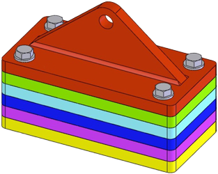
Using the ![]() Magnetic Block tutorial, start by following the tutorial steps to complete. Include all your drawing files (proper naming convention) in a folder similar to: td2-1_d-joe_mag-block as an example, as your course section and name would be different. Use the same naming convention for all of your files for full marks.
Magnetic Block tutorial, start by following the tutorial steps to complete. Include all your drawing files (proper naming convention) in a folder similar to: td2-1_d-joe_mag-block as an example, as your course section and name would be different. Use the same naming convention for all of your files for full marks.
Note Steps 61-69 are to be ignored because of the newer version of Solidworks we are using.
Major steps include:
- Steps 01-09, Create rectangular base for the slab shape
- Steps 10-18, Make standard holes using the hole wizard
- Steps 19-33, Using the configuration manager, also make tapped holes also using the hole wizard
- Steps 34-45, Create the crane hook bracket
- Steps 46-59, Put together the crane hook/slab assembly through mates
- Steps 60-67, Weld the crane hook to the first slab on two sides (**note**, steps 61-69 are out-dated, omit these steps, no separate assembly file required, but process is similar, i.e. access weld feature in "Assembly Features" button and use weld configurations from omitted steps where necessary)
- Steps 70-80, Add the balance of slab pieces to the parent assembly
- Steps 81-83, Add different colours to each part
- Steps 84-95, Use toolbox to insert washers and bolts
- Create an assembly, slab, and crane hook ortho/ISO drawings with dimensions, named correctly
- Hand your whole folder including the assembly, models, and drawing(3 sheets), all with jpg's (4 SW proprietary files, 6 jpg's )
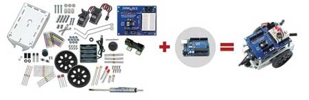
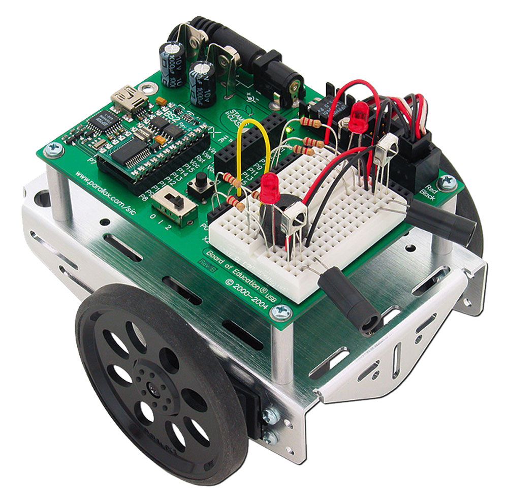
Boe-bot Robot
The Boe-bot is a great project to build and program. In-fact we use it as part of the Computer Tech courses to build, program, drive, add more functions to have it do some neat things. This is also a great project to build as an assembly with all it's intricate parts and being familiar with it before working on it is a big benefit. Most parts you will have to make from scratch, which is the intention in this project.
Boe-Bot Support Information
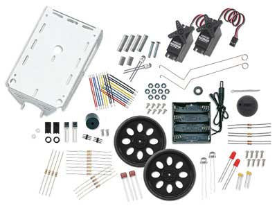
Drawing a boe-bot, you can use the actual unit to measure off of, but if you can access on-line information that gives you the exact dimensions, this can help you create a more accurate and quicker result in your reproduction and digitization of the boe-bot. When first getting the boe-bot kit, you would have to follow instructions on putting it together from the ![]() boe-bot manual, which would also show you what parts go where.
boe-bot manual, which would also show you what parts go where.
Some component information can be found on the Parallax web site which they sell the usb boe-bot for example:
- Brushed-aluminum chassis with mounting holes
 drawing link
 - Parallax Continuous Rotation Servo Dimensions: 2.2 x 0.8 x 1.6 in (55.8x 19 x 406 mm) excluding servo horn drawing link
- Dimensions for the Boe-Bot Robot drive wheels dimensions link and 1" Tail wheel ball
- Board of Education development board with a BASIC Stamp 2 micro-controller manual link
- Battery holder
 close-up image with case dimensions: 3.12 x 2.31 x 0.67 in (8 x 5.7 x 1.7 cm)
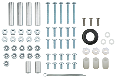
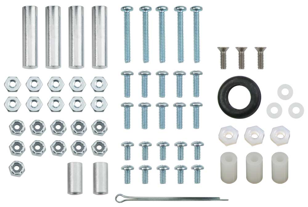
The following list shows the ![]() hardware fasteners used to support and fasten all of the boe-bot components:
hardware fasteners used to support and fasten all of the boe-bot components:
- 1/16" cotter pin
- 3/8" #4-40 pan-head screw
- 3/16" #4-40 flat-head screw
- 7/8" #4-40 pan-head screw
- 1/4" #4-40 pan-head screw
- 1" round #4-40 aluminum standoff
- 1/2" #4 aluminum spacer
- Rubber grommet
- #4 nylon washer
- #4-40 nylon core locknut
- #4-40 nut
- #4-40 Nylon nut
- #4 Nylon spacer, 1/2"
Remember you may find fasteners in the SolidWorks toolkit, otherwise you will want to use McMaster-Carr to download specific fasteners to use with your model. Although a lot of the parts on the boe-bot are custom and therefore not readily available, you may find the odd component from online CAD part suppliers that you could download, to use with your model.
Boe-Bot Build Steps
Using the actual parts create a digital 3D CAD model of the boe-bot with appropriate colours/textures using the following general steps:
- Start with the sheet metal frame then locate all mounting holes - step resource doc
- Create the servo and create the assembly by bringing in the frame first, then the servos, use toolbox for mounting screws
- Create the two front flat wheels and a back sphere wheel, then bring into the assembly and use toolbox for mounting screws, the cotter pin you may download
- Create the circuit board as a separate part,
- Create the round stand-off mounts with threaded holes
- Electronic components such as the as the bread board, BIOS chip, power switch, reset button, power pins, servo jacks, capacitors, etc. can be part of the bread board part
- Create an assembly drawing, and for each of the major components made such as the frame, circuit board, wheel, and servo motor (5 drawing files)
- Hand in your main project folder holding all parts, assembly, drawing files including JPG's
There are many small features that can be drawn in, but suggest for the electronic components, to draw the basic geometric shapes first, then if you have time, you can go back and improve the detail. For example the bread board has a pattern of pin contact openings that can be made using the pattern tool

For advanced additional challenge, design and draw a support function for your boe-bot. Ideas can be reviewed on the parallax boe-bot accessories, to see what other possibilities there are. This will require some additional research and time to complete.
Evaluation:
Ensure that you have included all required files and folders named in the correct naming conventions. Sample naming conventions have been provided above, which you could just copy and change the course section and name. Remember dimensioning standards, view placement, spacing, and object scaling.

| Evaluation Breakdown Component Descriptions | Marks |
|---|---|
| Always double check that you have completed all components for full marks. | |
| Magnetic Block - Model/Assembly built, ortho/ISO,assembly and part DWG's | 50 |
| Boe-Bot - Model/Assembly built, ortho/ISO,assembly and part DWG's | 70 |