Unit 4: Grade 10 Technological Design - Robotics - Introduction to SolidWorks
This unit will introduce you to SolidWorks, allow you to print your projects with our 3D printer, and create drawing files of your model. Being familiar with past sketching projects, 2D Draftsight, 3D Sketchup, the design process, orthographic views, dimensioning, and creating drawing files sets up students base knowledge and understanding of engineering standards and support to focus on more complex challenges.
Course Units and Descriptions
Use this table for an overview and navigate to each of the course unit pages.
| Unit | Description |
|---|---|
| Review course outline for more details | |
| 1 | Careers & Safety- Intro, computers, organization, and careers |
| 2 | Technical Sketching- freehand sketching, ortho, dimensions, ISO views, custom ortho design |
| 3 | Basic 2D & 3D CAD Intro- 2D coordinates, lines, ortho views, 3D drawing, and custom design digitized |
| 4 | 3D Parametric Design- 2D sketch, 3D parts, feature tools, drawings, exporting for 3D printing |
| 5 | Sheet metal Design- thin material design, folds, assemblies, 2D print, project design, testing, and build |
| 6 | Robot Assembly- part reproduction, part assemblies, custom function design and build |
| 7 | Web Portfolio- Showcase course work, projects, and understanding with web portfolio and presentation |
Unit Content Activity Quick Links, Click to Jump to Specific Activity!

- Unit 4, Act. 1: Creating a 3D Model Using SolidWorks
- SW Intro, Key Terms, Files, Folders, Resource links, (Create) Expert Areas, Step Block (SB) Model, SB Prep, SB Steps, Evaluation
- Unit 4, Act. 2: Creating Orthographic Drawings
- Unit 4, Act. 3: Printing Your Model in 3D
 Unit 4, Act. 1: Creating a 3D Model Using SolidWorks (SW)
Situation:
Now that students have experienced and gained knowledge and skills on engineering communication n standards, methods, and process, looking at a "bigger tool box" with a lot more tools such as SolidWorks will allow for more opportunity to design very specific and detailed designs..
Problem/Challenge:
Two unique research pages on Solidworks Expert 2D Tools and 3D Features will be created with supplied template to research and share with class. Students will review and learn about SolidWorks and it's history, then using our familiar object, the step block, create the object in SolidWorks.
Investigation/Ideas:


Solidworks Introduction
Creating 3D model in SolidWorks with the step block should be straight forward using the steps, pictures, and instructions given. Students should be aware of key information as they go through this step block tutorial such as parametric driven, integrated 3D CAD/CAM/CAE solution, used by discrete manufacturers for mechanical engineering, design and manufacturing. With all of the previous experience with sketching, drawing views, selecting the front view, dimensioning, 2D drawing, and 3D introductory modeling, this should be easy to pick up the basics, as you are already familiar with the previous programs used. The tutorial in the next section will guide you step by step to support the creation of your customized key ring accessory.
Key Terms
- CAD- Computer Aided Designing is a technology concerned with creation, modification and optimization of a design - (SolidWorks, ProE, Catia, etc.)
- CAM- Computer Aided Machining is a technology which involves computer systems that involve, plan and control manufacturing process - (SolidCam, MasterCam, HMS Works, etc.)
- CAE- Computer Aided Engineering helps us to do the analysis of the CAD created product - (Symulation, Ansys, Abaqus, etc.)
- design intent - how your model behaves when dimensions are modified
- parametric - features and relationships of the model, which is intended to capture the product’s behavior
- constraints - component characteristics between two or more entities defining that component and/or property
- relations - is a relation among the specification space and the description space, such that the related CAD-function is preserved
- fully, over, and under defined - does your object drawn have the right amount of information needed by the program
- best practices - are generally good drawing habits to keep organized, create less problems, and ease of work
File Formats & Handing in Work

There are several file formats that your work can be saved in. Your model work in SolidWorks has it's own proprietary or native extension unique to its part files. Here are examples of some of the most common file formats and naming conventions you commonly used:
- SLDPRT - SolidWorks model part: td2-1_d-joe_2d-step-block_60x30x30mm.sldprt
- EPRT - Epart file allows users to view with a free e-drawings application: td2-1_d-joe_2d-step-block_60x30x30mm.eprt
- STL - Common CAD standard STereoLithography for use with Cura to convert file to print 3D: td2-1_d-joe_2d-step-block_60x30x30mm.stl
- JPG - Joint Photographic Experts Group: td2-1_d-joe_2d-step-block_60x30x30mm_dwg.jpg (note -dwg or -d, as to not overwrite your model jpg that was possibly saved file earlier )
- PDF - standard Portable File Document: td2-1_d-joe_2d-step-block_60x30x30mm_d.pdf (note -dwg or -d, as to not overwrite your model pdf that was possibly saved earlier)
For this project practice, you hand in the above file formats in a folder using CAD folder/file naming convention: Using your USB flash drive, create a folder, for example: td2-1_d-joe_step-block. For the file naming, save correctly the first time (to prevent future file reference problems) with the proper file naming convention, ex: td2-1_d-joe_step-block_P_60x30x30mm.SLDPRT. The underscores separate sections of the file/folder name, dashes separate but keep the file name sections together, the P represents "Part" vs other file types such as assemblies and drawings, and the last part is a description, in this case the size of object.
Why the need for using a folder...

when working with 3D CAD programs, a model part is saved and then additional file types are also created based on that model part, those additional files saved, such as drawing files and assembly files not yet looked at, are directly dependent on that model file. By saving in the same folder, keeping model file names simple, short, and descriptive will allow all projects working seamlessly together. In a larger project with multiple model parts, assemblies, and drawing files, if the files are save in different locations, the dependent files remember where they are, so if moved will not open. If model parts are renamed after, dependent files will not open or function as they will not be able to find the original. Moral of this big tip, save all of your CAD related files in one folder and keep file names simple, short, and descriptive.

Resource links
There are several resources on the web that can be helpful when familiarizing yourself with SW, a program of this caliber.
- Comparison of CAD Editors
 Selecting a Workstation
 CAD History
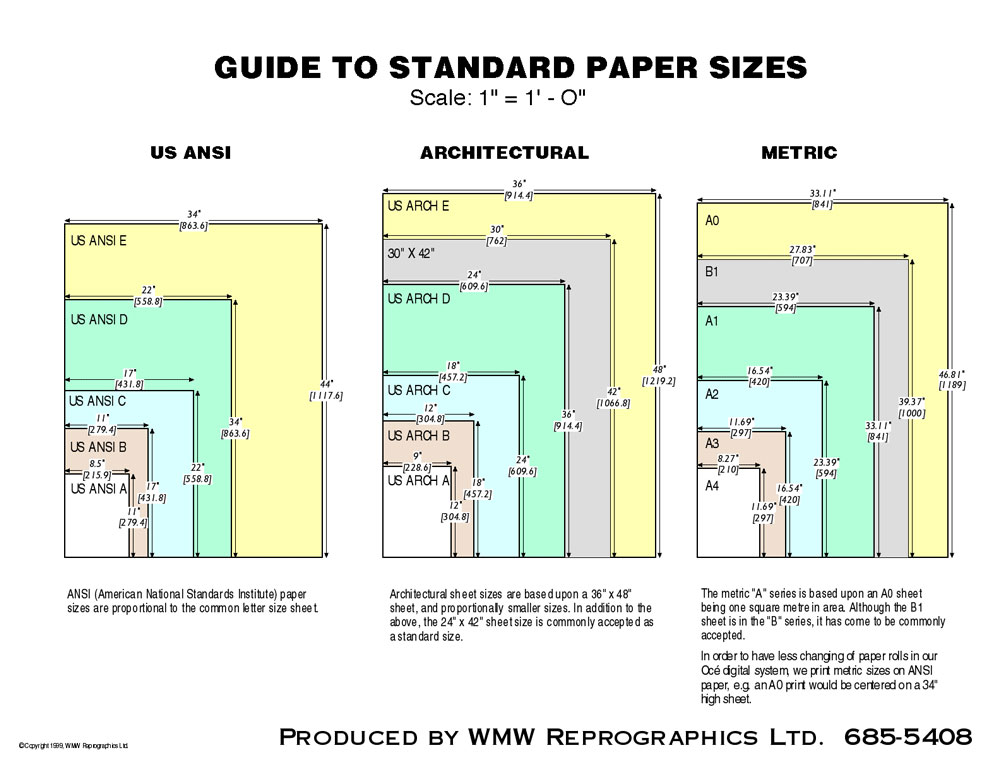
- Imperial or Metric ?
- Wikipedia on SW
- SW Main Site
- SW Basic Introduction
- SW Web Help
- SW Tutorials
 SW in 10 Minutes, 13.5
- SW machine design, 5.27
- SW overview all in one, 5.07
- Intro to SolidWorks, 14
- Intro to SW
- SW Intro, 11.46
- Guide to SW 2014
- SW Modeling, play list
- SW Gripper intro, 11.48
- SW Tips 22
- 30 SW Tips, 29.11
- 10 Golden Rules
- 3D Modeling Best Practices
- Part Modeling Best Practices
- Best Practices, 22.11
- Design Like a SW Wizard, 46.26
Create/Construct:
Expert CAD Research and Share

Create two unique information pages, one for 2D sketch and 3D feature tools. First come first serve for topics that can be selected from a digital help list - 2D Sketch and 3D Feature tools
The Expert CAD tool pages will be a place to share your selected 2D sketch and 3D feature tool information with your peers in the school pick-up folder, after you have handed in the school class drop-off folder for marks. Students will:
- Using the class Google classroom, access the SolidWorks Expert CAD Tools sign-up sheet, put your last initial, first name, select and type in one unique 2D and 3D SolidWorks tool that is used to create various CAD related tasks
- Research the topic (save your link resources)and then practice the process, so you become an expert with those tools
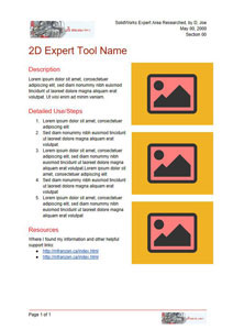
- Make a copy of the provided 2D and 3D Google template files found in the Google classroom to create your Expert CAD Tool pages
- Update file name, the the header information, then add the name of the tool to the title of research page
- Create a description of the tool - what it is, what it does, why you would use it
- List the steps needed to use/apply that tool in point form
- Add your resource links for your understanding and other related great links (minimum 2)
- Replace picture holders with relevant and related pictures supporting steps
- Have a unique partner, who has not reviewed anyone's project yet, to review and give you the "thumbs-up" if they understand/tested the expert tool you have shown and put their name in the bottom, example: Checked by: D, Jane
- Download as Microsoft doc, and submit to school drop-off folder in the file format naming convention: 2d-tool-name_d-joe.docx or 3d-tool-name_d-joe.docx to be marked and later shared in the pick-up folder for all students to use as a resource later on when needed
Students become the expert in the tools they researched and are to share their learning and application of those tools learned with other peers when called upon or if peers need assistance. You are expected to make the effort to assist those that come to you for your expertise using the tools that you researched and tested.
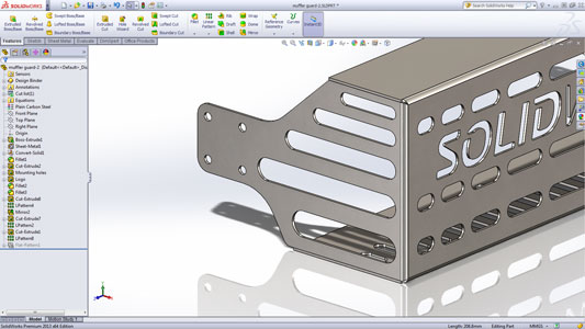
Step Block 3D CAD Project
Create a simple step block following the steps and support pictures below. As deceptively easy this assignment may be, by following the steps, keep in mind the underlining concepts in front view selection, 2D sketching, 3D modeling, dimensioning standards, and common sense reasons why the project is done they way it is with respect to Engineering standards and communications of ideas.
Part/DWG Organization
Sheet Size
Std's
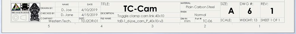
Thinking ahead, making up templates for your work will make your work easier, faster, and more professional. Below is an example of a drawing information block that has been populated automatically from information in the model part using auto-fill fields. This is done by inputing the information in the part model file, then creating the drawing file with linked fields. For your benefit, a template has been created similar to the one below showing just the information block on a "A" standard sized sheet, which is the same size you use to write your notes on daily (8.5" x 11").
Ensure your front view that is drawn, is in-fact the correct front view based on the three rules. Remember folder/file use and naming convention, name features in feature tree, add the material, appearance, summary information, and custom properties for each part made. The properties you fill in for your model will keep record of, organize, and auto-fill your DWG template fields later when you bring your model into this template drawing file. Examples show below will give you more visual details of what is explained above.

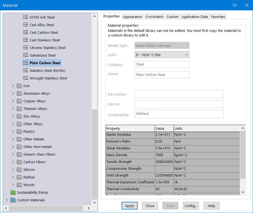
Materials
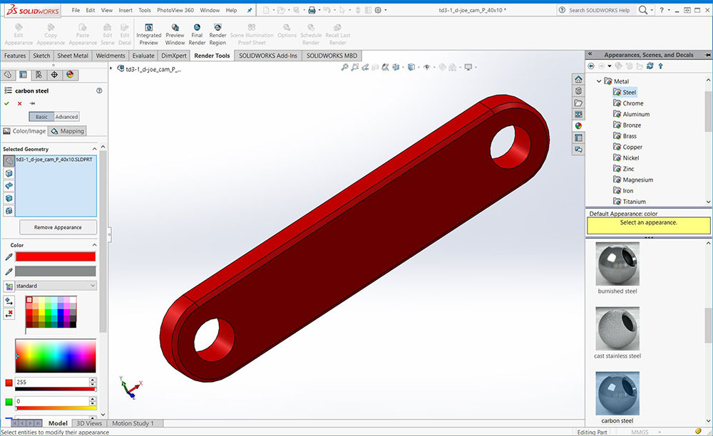
Appearances

Summary

Custom
![]() Ensure you have a folder, example folder name: td2-1_d-joe_step-block inside your class folder on your USB flash drive so that you can save all related model files together for ease of use, organization, and for handing into the drop-off folder later. For files use appropriate file naming convention, example: td2-01_d-joe-step-block_P_60x30x30mm.sldprt
Ensure you have a folder, example folder name: td2-1_d-joe_step-block inside your class folder on your USB flash drive so that you can save all related model files together for ease of use, organization, and for handing into the drop-off folder later. For files use appropriate file naming convention, example: td2-01_d-joe-step-block_P_60x30x30mm.sldprt
Step Block Steps and explanation breakdown:
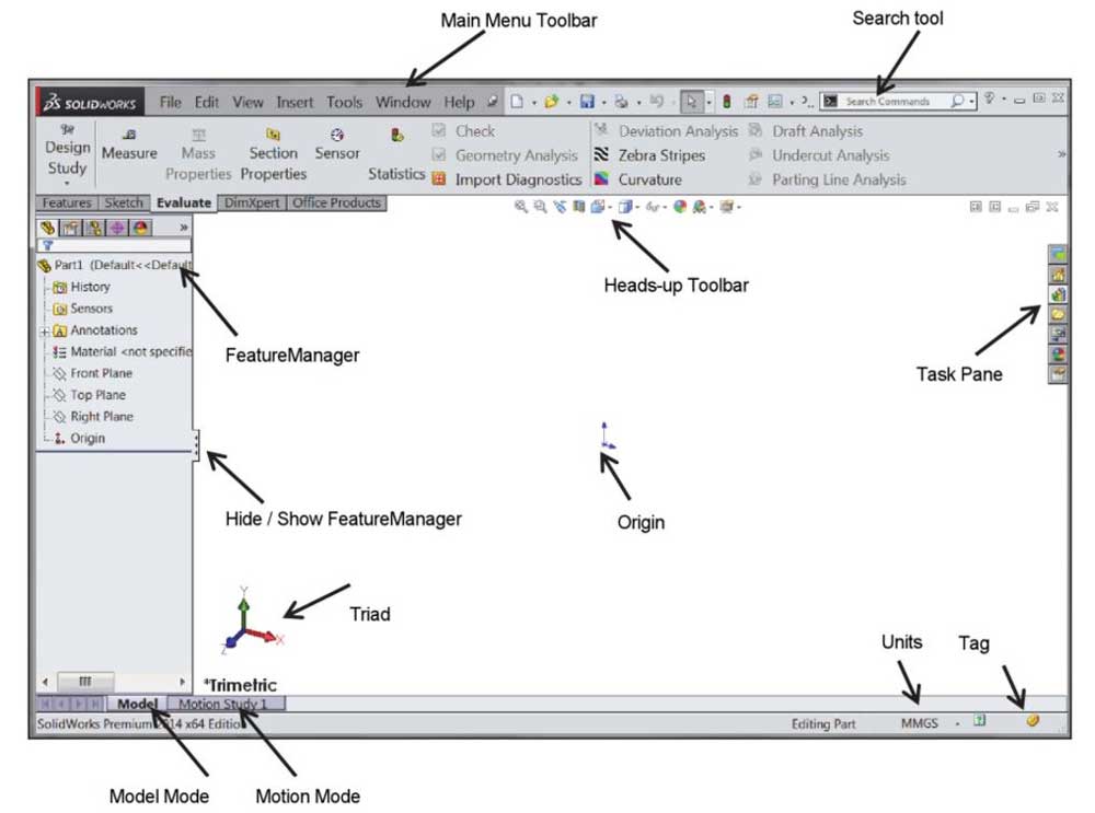
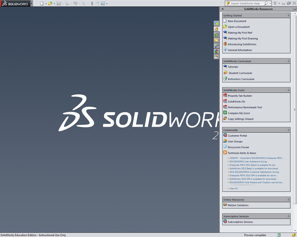
- Start-up: Run SolidWorks application, and you will get an opening screen
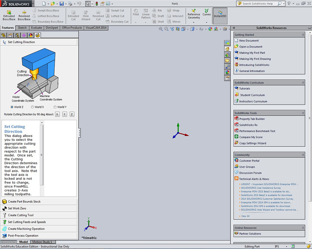
- New Part: Select new model part
- Model Workspace: Ensure you have ANSI standards and millimeters by selecting Options at the top, selecting Document Properties, and ANSI is selected as the drafting standard, then select Units and check that your document is in millimeters. Fill in your summary and custom information as shown above section titled Part/DWG Organization
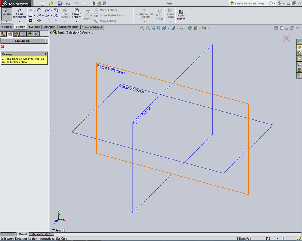
- Sketch / Plane: Select the Sketch tab at the top to bring you into sketch mode and select your 2D sketching tool, in this case the line tool
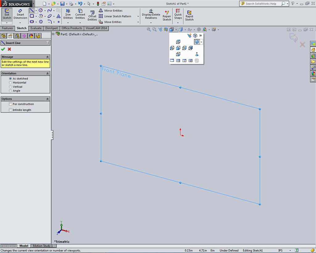
- Front Selected: Select the plane you want to sketch on, in this case it is the front plane, the other two planes should disappear
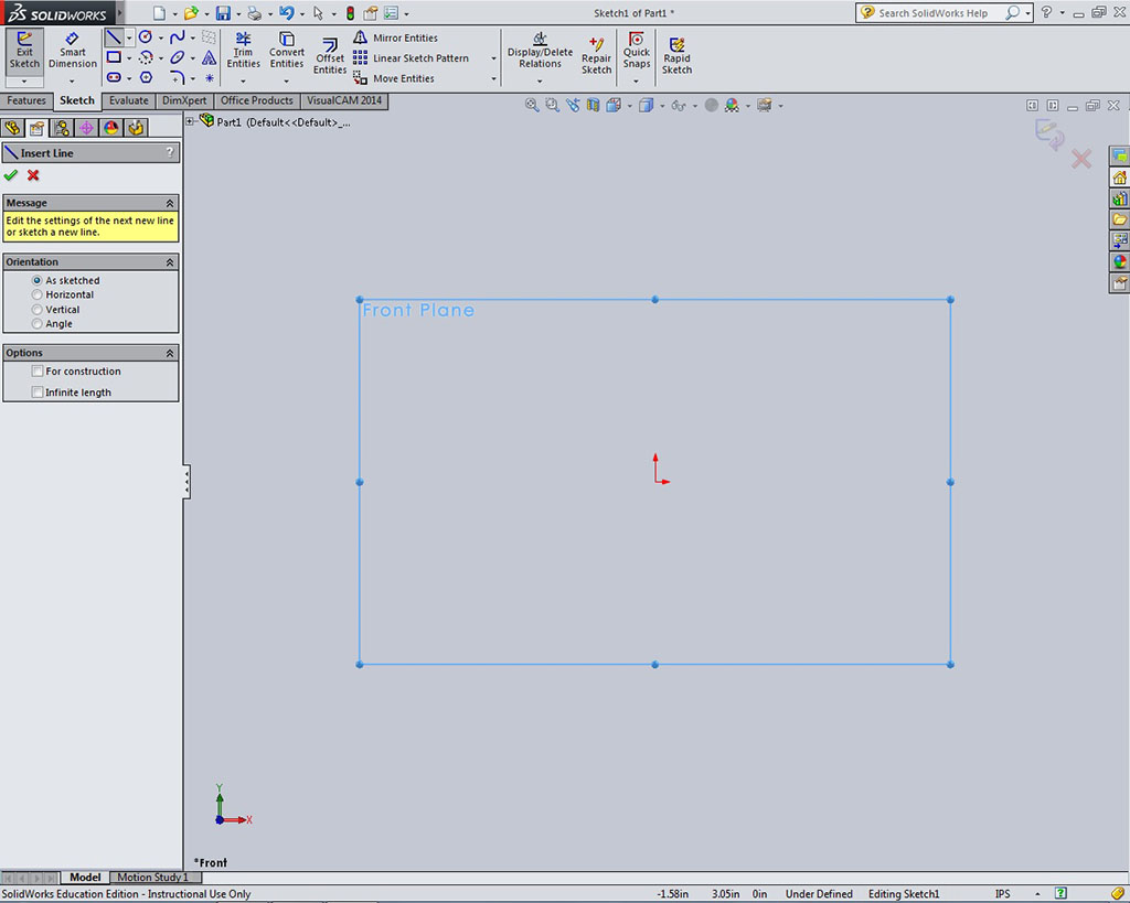
- Front View: Select the View Orientation icon on the workspace near the top, and select the front view or use shortcut Ctrl +1 so you are looking straight at the front view. Another option is to right click on the front view and select the Normal To icon. it is always a good habit to sketch on a flat plane
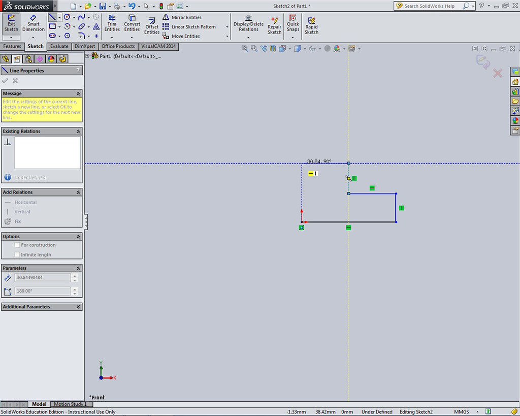
- Sketching: Starting at the x,y origin, start creating your object using direction snaps to keep lines straight and/or perpendicular your last line to draw the step block front outline
- Snaps: Above image shows the direction snaps in action, you will need to hover the mouse and then click one you have to snap show-up to draw the approximate shape, don't worry if it is not the exact right dimension, as they will be fixed later. The second last line segment use the snaps to align the last line starting point to line-up with the origin and close your shape. This is very important, make sure your object shape is closed with no openings or stray lines, otherwise the part can not be extruded later
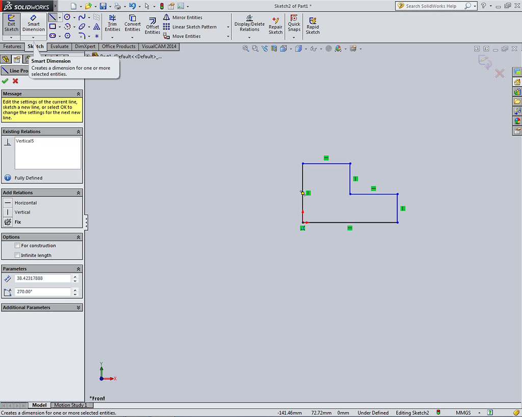
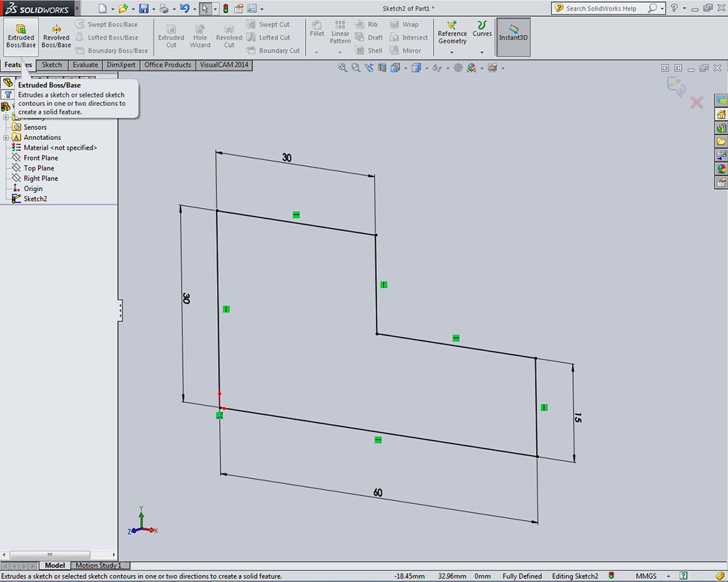
- Dimensions: Once finished drawing your object, select Smart Dimension at the top above the sketch tab, and dimension your object being careful not to over define or under define, meaning putting the right amount of dimensions needed. Adding relations instead of dimensions in this process can be advantages, improve design intent, and less cluttered when possible.
 You must save your file to your USB flash drive in a folder, for example: td2-1_d-joe_step-block. Save file often through-out your project creation and name it properly the first time (to prevent future file reference problems) with the correct file naming convention, ex: td2-1_d-joe_step-block_P_60x30x30mm.SLDPRT
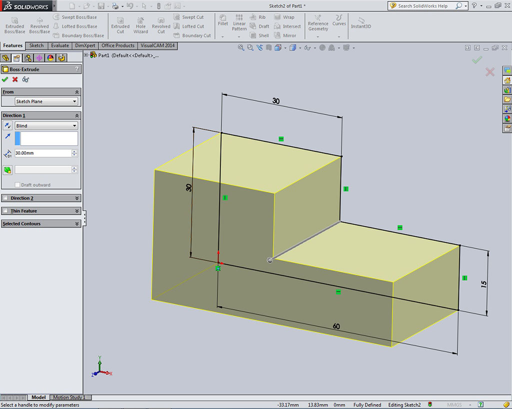
 - Extruding: Once sketch is fully defined, meaning the drawing has the right amount of dimensions and relations, click the green check mark and select the Features tab. On the Features tab, you will be selecting the 3D feature you need to finish your object, and commonly this will be the Extruded Boss/Base, then drag or enter the desired depth and direction of your object
- Part Extruded: Once you have the right depth (Z axis distance) select the green check mark to complete. Note a yellowish extrusion does not show up, it is because there is something wrong with your shape, such as a stray line, object not closed, etc. which you will have to fix first before extruding
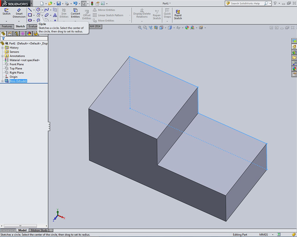
- Circle: Next, you will need to make the hole by selecting the Sketch tab, then selecting the circle tool and clicking on the surface where you want to create the hole. It is not critical that it is located exactly, nor does it need to be drawn to exact size at this point
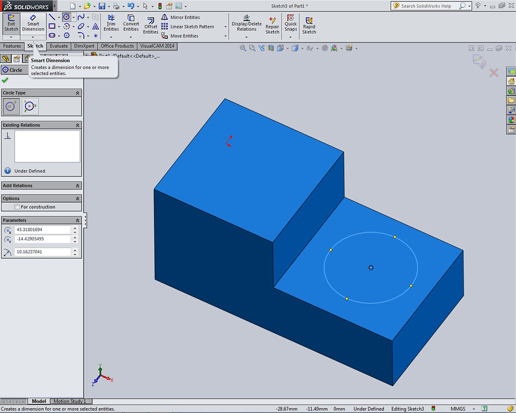
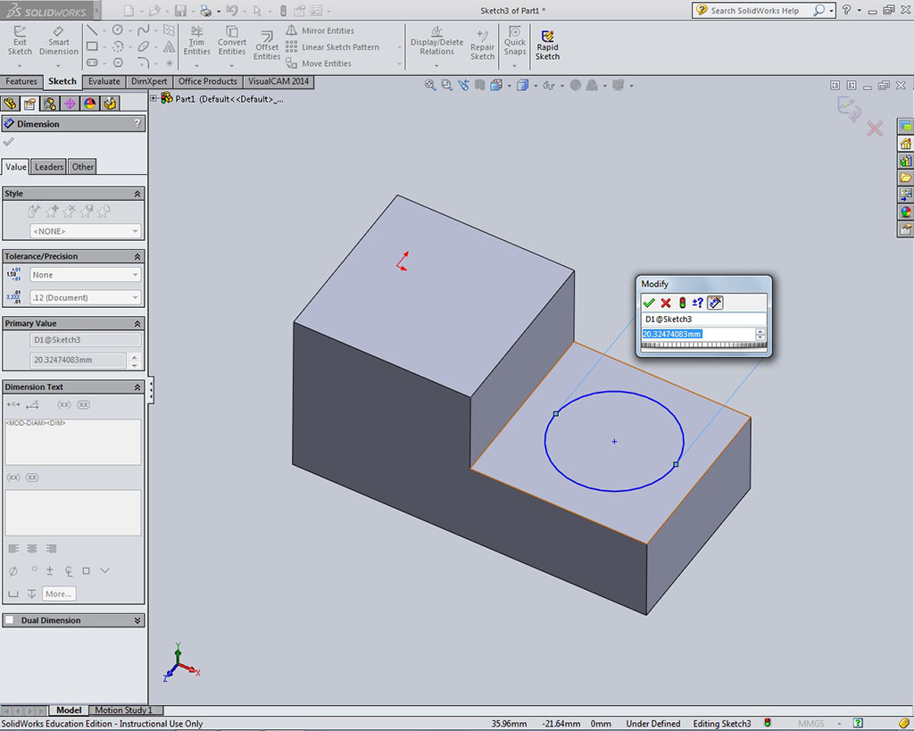
- Dimension Circle: Once circle is done, select the Smart Dimension button, and dimension the circle itself and confirm and enter the correct dimension
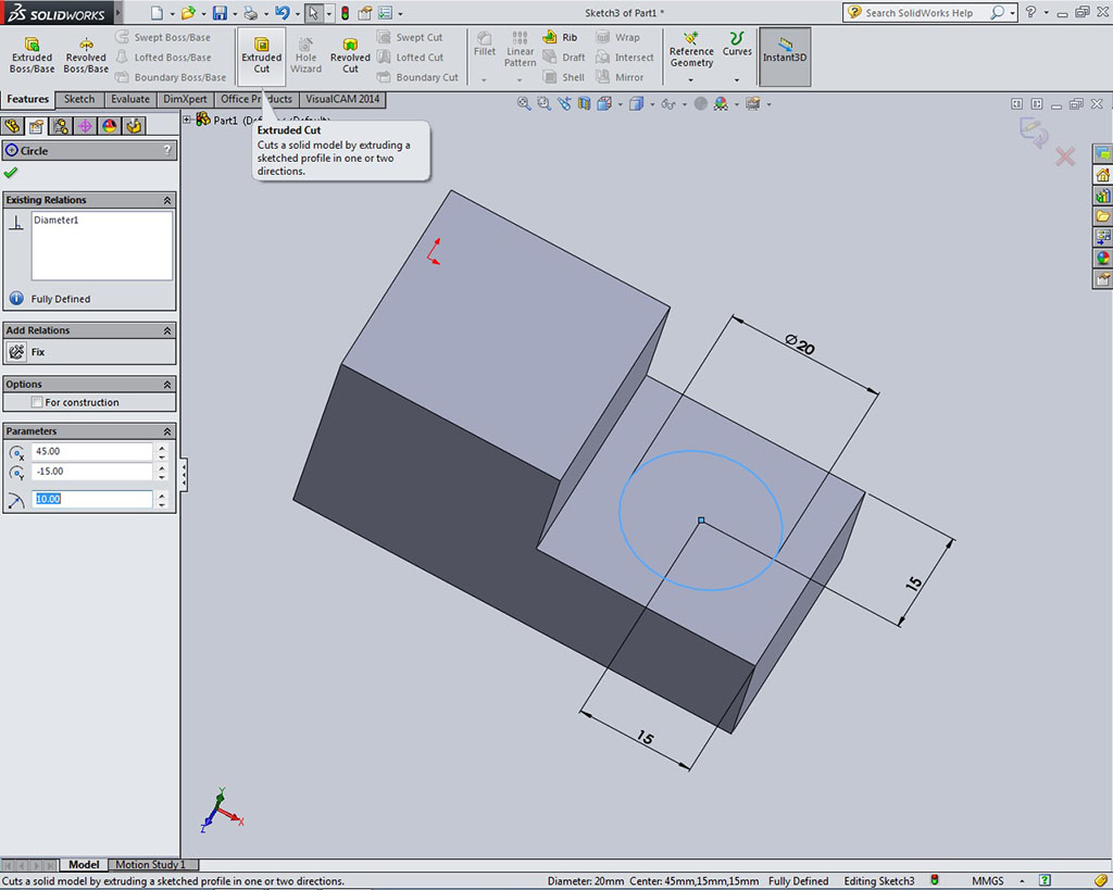
- Circle Location: Also dimension the circle location using the centre circle point and sides of object which should fully define that feature and you can click on the green check mark to finish
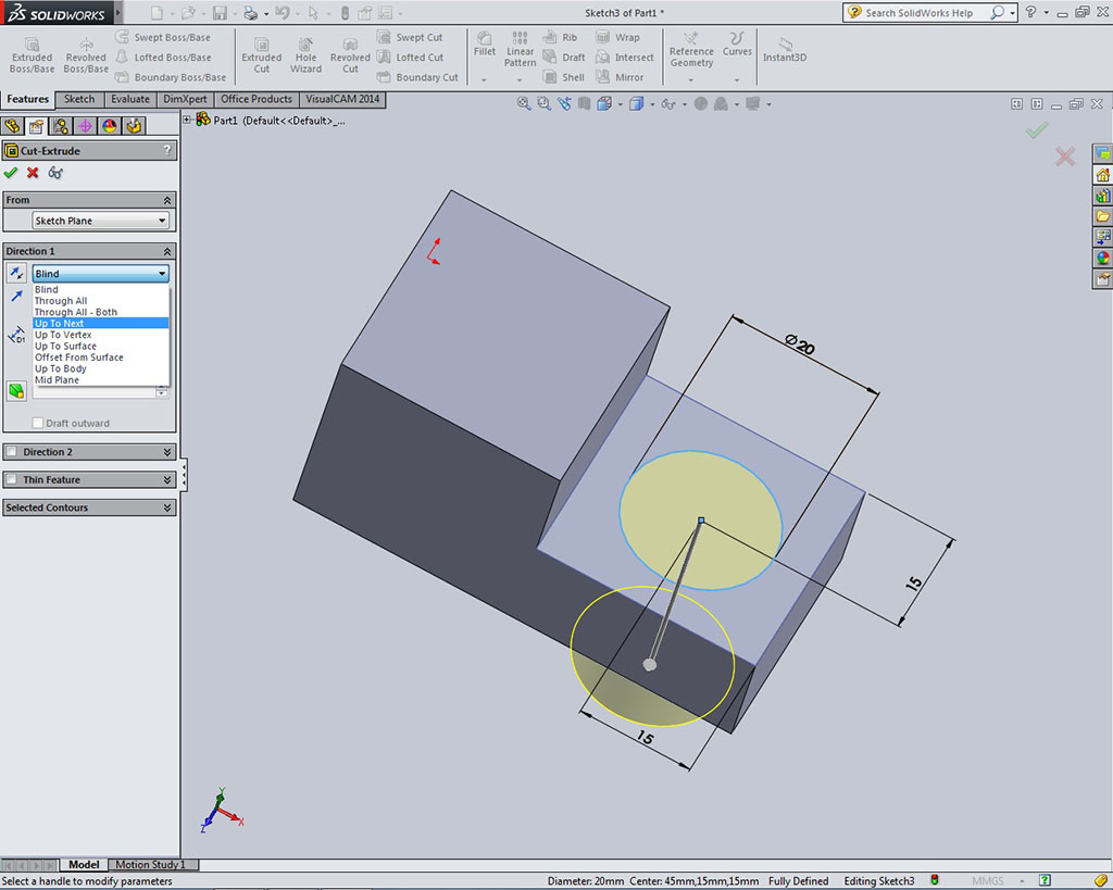
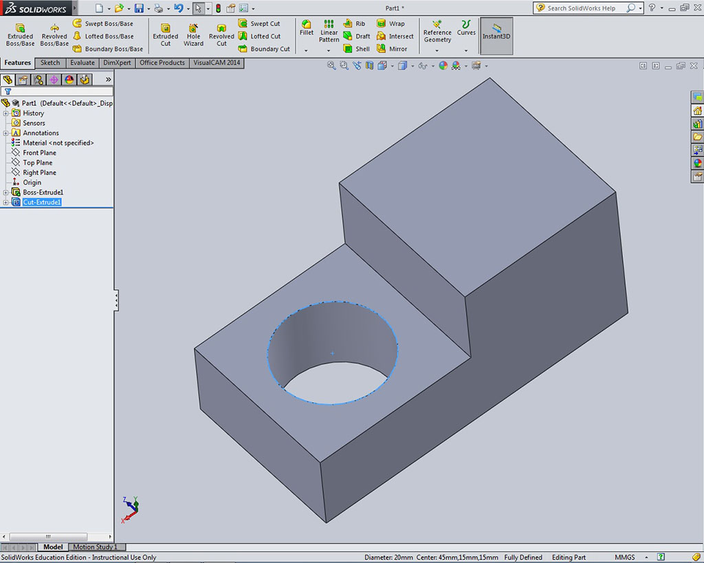
- Circle Hole Depth: Select the Features tab again and this time you will select Extruded Cut, which will remove material. In the properties manager change direction 1 to Up to Next for proper depth of hole removal, then click on the green check mark to complete feature
- Hole Complete: Once hole is complete turn your object to show the most detail for later showing in an ISO view. You could try just selecting the Orientation View icon above and selecting ISO view, but it may not be the best view
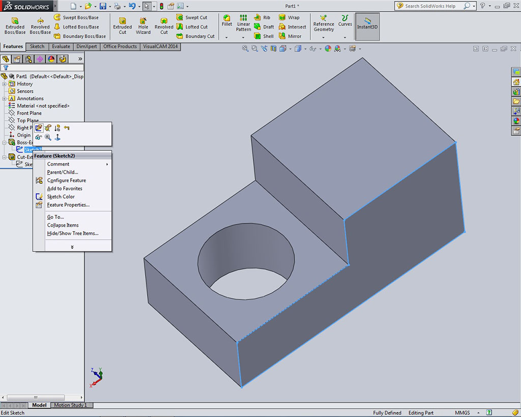
- Possible Edits: If you need to modify, change, or delete anything you have created, by right clicking on the feature or sketch item in the Feature Manager Design Tree, will give you those options. This is why it is a good practice to to name your features in relation to model for later identification
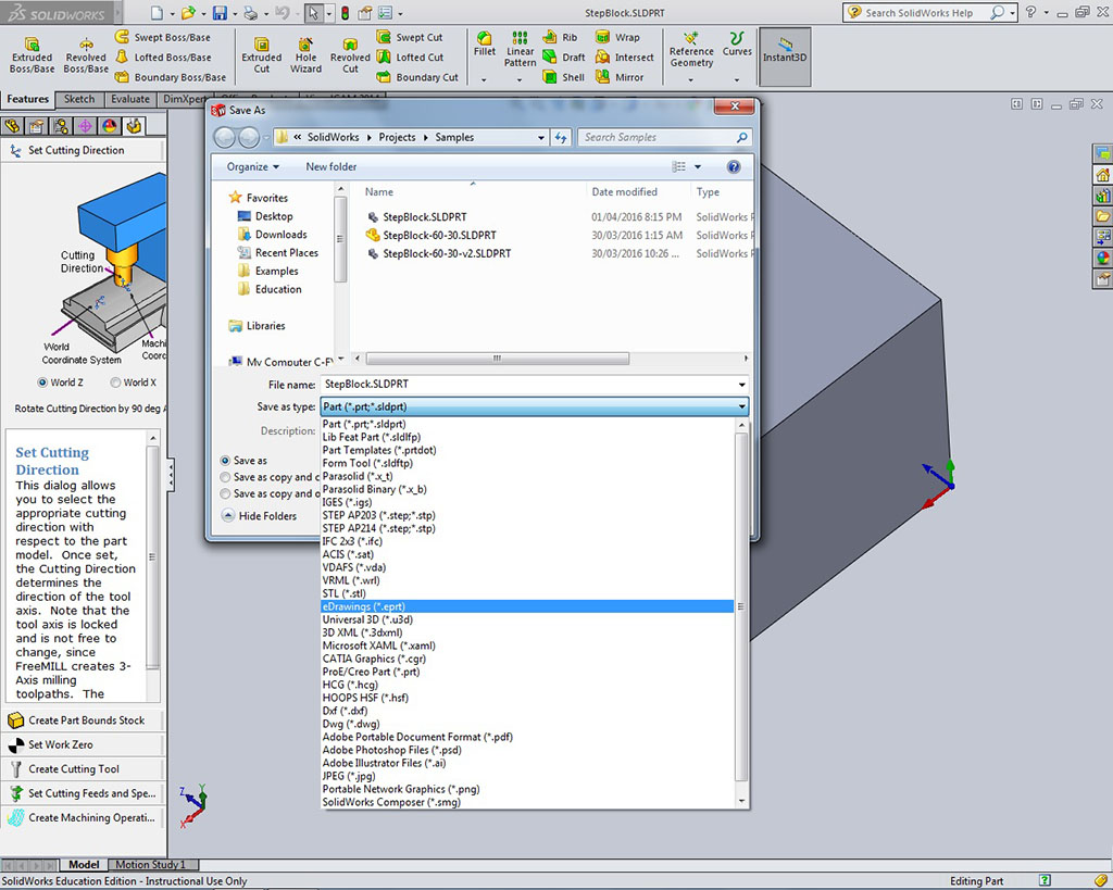
- File Types Available: There are several file types available, but for this project you will save your tdj_stepblock_d-joe in five formats for practice for this project only in the follow file types; its proprietary file format: SolidWorks Part Document (.SLDPRT), Free part viewer file Epart (.EPRT), Common CAD standard STereoLithography (.STL), picture file (.JPG) and lastly a portable file document (.PDF) format. It is important to add _P for part at the end of your file for the JPG file type, so they do not get over written when you save your drawing file later
Step 1
Start-up

Step 2
New Part
Step 3
Model Workspace
Step 4
Sketch / Plane
Step 5
Front Selected
Step 6
Front View
Step 7
Sketching
Step 8
Snaps
Step 9
Dimensions
Step 10
Extruding
Step 11
Part Extruded
Step 12
Circle
Step 13
Dimension Circle
Step 14
Circle Location
Step 15
Circle Hole Depth
Step 16
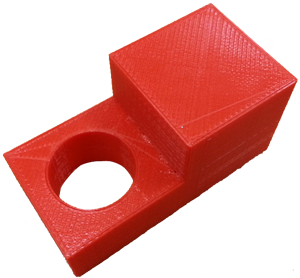
Hole Complete
Step 17
Possible Edits
Step 18
File Types Available
Evaluation:
For this activity, you only need to hand in your Expert 2D/3D research papers. The Step Block will be handed in together with your drawing that you will complete in the next activity.
| Evaluation Breakdown Component Descriptions | Marks |
|---|---|
| Always double check that you have completed all components for full marks. | |
| Expert 2D Sketch Tool: New tool/process name/description, steps, sample, and links | 20 |
| Expert 3D Feature Tool: New tool/process name/description, steps, sample, and links | 20 |

Unit 4, Act. 2: Creating Orthographic Drawings
Situation:
Having experienced some model creation with SolidWorks, will give you the opportunity to practice using more tools with SolidWorks for drawings.
Problem/Challenge:
Complete a drawing exercise on the step block model earlier created using the supplied template. Views must be placed, based on the three rules for the front view, which should already been taken into account when drawing the model. Scale and space for dimensions must be taken into consideration. Overall and detail dimensions must be placed appropriately considering spacing and locations. Shaded ISO and information block will also need to be completed. Using feedback from the instructor, make your key ring is done correctly following the same process as the step block..
Investigation/Ideas:

CAD Model and Drawings
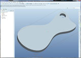
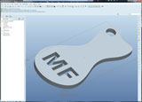
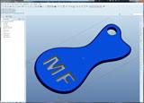
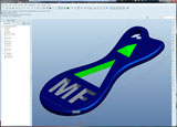
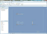
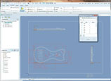
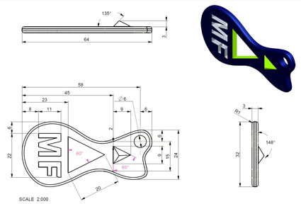
For this activity you will follow a set of steps to create the Step Block then have the opportunity to apply the steps to your key ring accessory (KRA). Below shows a sample key ring accessory created, first by model, then the drawing.
CAD Model Process
Completing your Step Block in the last unit activity should allow you to apply the same steps to build your key ring accessory (KRA). Below shows some steps done by Creo Elements (similar CAD application) starting from your 2D sketching to using your 3D feature tools to finish the model. Note colour appearance was also added.
Model Sample 1
Model Sample 2
Model Sample 4
Model Sample 5
Model Sample 7
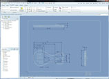
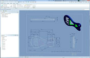
CAD Drawing Process
Making drawings is important to do as it communicates a lot of information about your model, that would not normally be known from just looking at the model alone. Below shows thumbnail examples of a key ring accessory drawing being created:
DWG Sample 1
DWG Sample 2
DWG Sample 3
DWG Sample 4
The basics of making drawings are similar in most CAD programs, the model file is used as a source for information to draw the views in drawing file. If something is changed in the model file the drawing will up date also based on the new changes.
Resources
- Imperial or Metric?
- Getting Started in Drawings
- Drawings
- Assembly & Part Drawings
- Generating drawing
- Saved Views
- Drawing and Detailing
- SN Drawing Blog
- CapU Drawing Blog
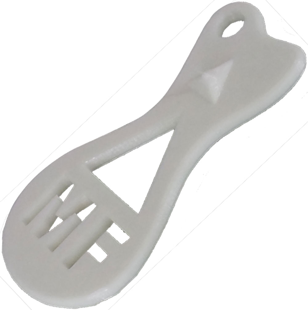
Your Key Ring Accessory Design in Solidworks
Once you have completed the step block, you now have a basic understanding of SolidWorks and can apply the same process to create your key ring accessory. Depending on your design you will have to try new feature tools and sketching techniques to build your design in SolidWorks. This is where your Expert 2D Sketch and 3D Feature tool operation peer support pages come in handy. If after looking at the support page and still having difficulty, discuss with owner for more details. Practice, experiment with with planes, construction lines, constraints such as center point, mid point, Further sketching tools such as trim/extend, offset, mirror, patterns, spline, arc, polygon, fillet, ellipse, text, etc may need to be used. Extruding a revolve and using features such as fillet, rib, shell, draft, sweep, loft, pattern, mirrors, etc may also need to be used. With many tools offered by SolidWorks, it is important not to get overwhelmed and patiently look at which individual tools will best help you draw/build your model.
3D Key Ring Accessory Design Considerations

To refresh your mind when creating your 3D mode from your original sketch design, there are several things you need to re-consider. Below is a reminder of the requirements and suggestions to keep in mind::
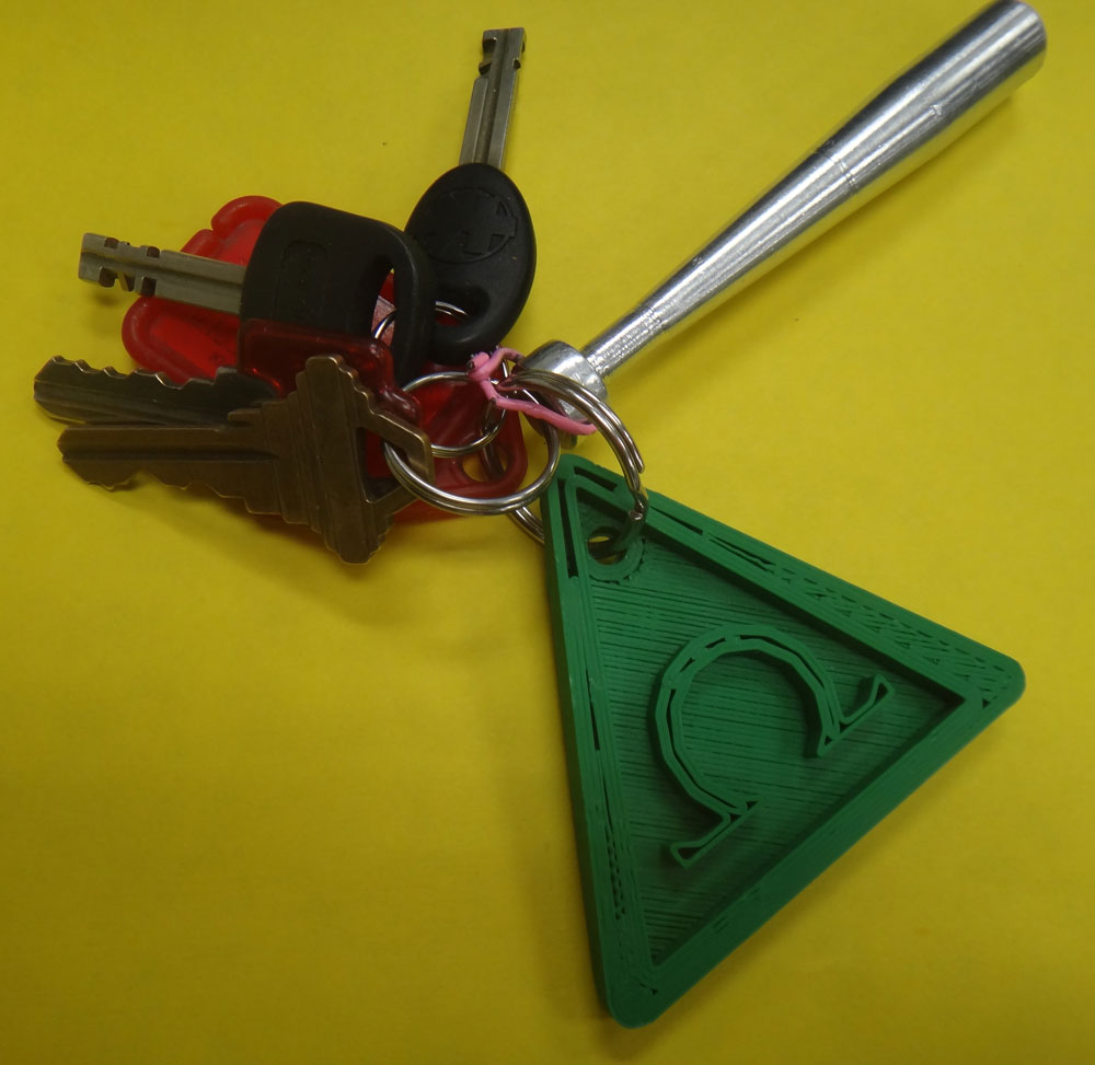
- Should have a unique (letter initials) and custom look identifying you as the owner of it
- Have at least 5 mm of material everywhere for print plastic strength
- Use a ruler if you are not sure physically how big your design will be (size of chap stick or eraser)
- Key hole for key ring must be a minimum of 5 mm in diameter
- Key hole must be placed in a practical location
- Thickness of key ring accessory to be a minimum of 5 mm
- Scale it appropriately, so that it may fit into your pocket or purse easily
- Add rounds to any sharp edges to minimize pocket holes and ensure safety
- Decide before which colour you would like to use for your project and buddy up with a group, so to minimize changing the filament colour roll
Create/Construct:

Using Templates
Sheet Size
Standards
SolidWorks generic drawing templates can be bulky and use a lot of unnecessary space and information specifically on smaller standard sheet formats. Using the supplied "A" sized custom template file that fits a standard letter sized sheet in landscape format is convenient and practical (shown below with all auto fields filled in for the sample TC-Cam part, with only the sheet scale left to enter) is found in the our class pick-up folder of the school's network. You will need to ![]() configure/tell SolidWorks (video sample process), 2.08 where your custom templates are, before you can use them.
configure/tell SolidWorks (video sample process), 2.08 where your custom templates are, before you can use them.
You have two options when using the provided template: dwg_A-land-ansi-mm-cp-1_mf.drwdot. ONE: You could use the pick-up template folder location (recommended), by copying the file location using ![]() your systems file browser, to add another template folder location to SolidWorks, under System Options in File Locations (icon wheel at top), as shown in video, but this will only be accessible at school, or TWO: You could also copy the template file from the school pick-up folder and put into a folder on your USB or H drive under SolidWorks/Custom/My-Templates folder (similar video process) and then inside SolidWorks, under System Options in File Locations (icon wheel at top), put that same folder location in, for your custom templates address, this way it is always avaliable with you on your USB.
your systems file browser, to add another template folder location to SolidWorks, under System Options in File Locations (icon wheel at top), as shown in video, but this will only be accessible at school, or TWO: You could also copy the template file from the school pick-up folder and put into a folder on your USB or H drive under SolidWorks/Custom/My-Templates folder (similar video process) and then inside SolidWorks, under System Options in File Locations (icon wheel at top), put that same folder location in, for your custom templates address, this way it is always avaliable with you on your USB.
For adding multiple sheets (more than one drawing in the same drawing file) with the same template, just left click on your first template and copy and paste to a new sheet as many times as you need. Note, for AutoFill Fields to work, you must have already filled in the appropriate information in your model parts, Summary and Custom fields, for the drawing fields to populate with the provided drawing tempate.
Creating Drawing
Below are the steps to create a basic drawing using SolidWorks. With Standard information blocks being quite bulky and a lot of unnecessary information, a template fitting a standard letter landscape has been provided. Note template shown below has had updates and will not look exactly as shown below, and remember to save with proper file naming convention and save often using the Ctrl s keys.
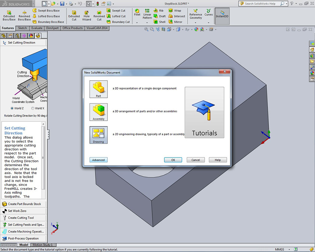
- New Drawing: Open new drawing window, and if in novice, select advance at the bottom to access other templates
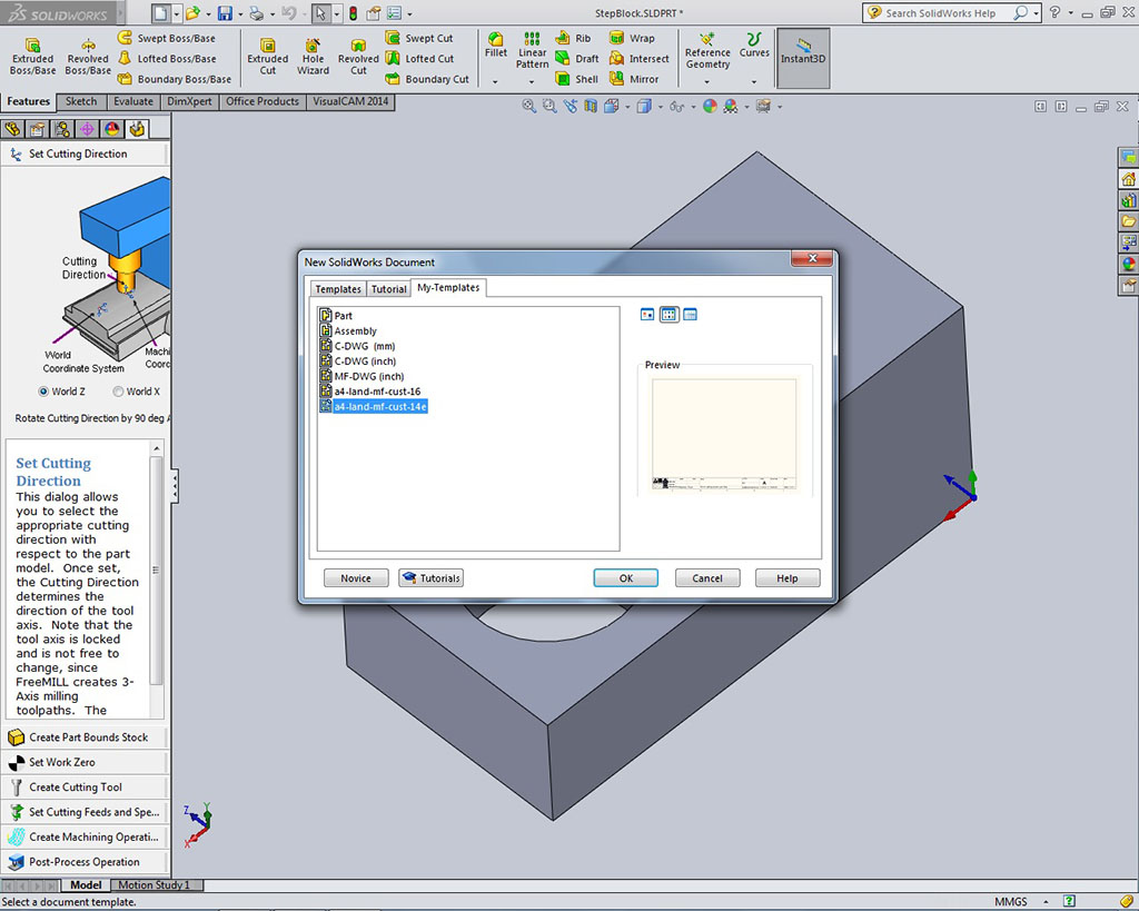
- Template Selection: With the advanced window, select the custom template folder you created earlier, and select the custom template dwg_A-land-ansi-mm-cp-1_mf.drwdot, you should see a preview similar to above
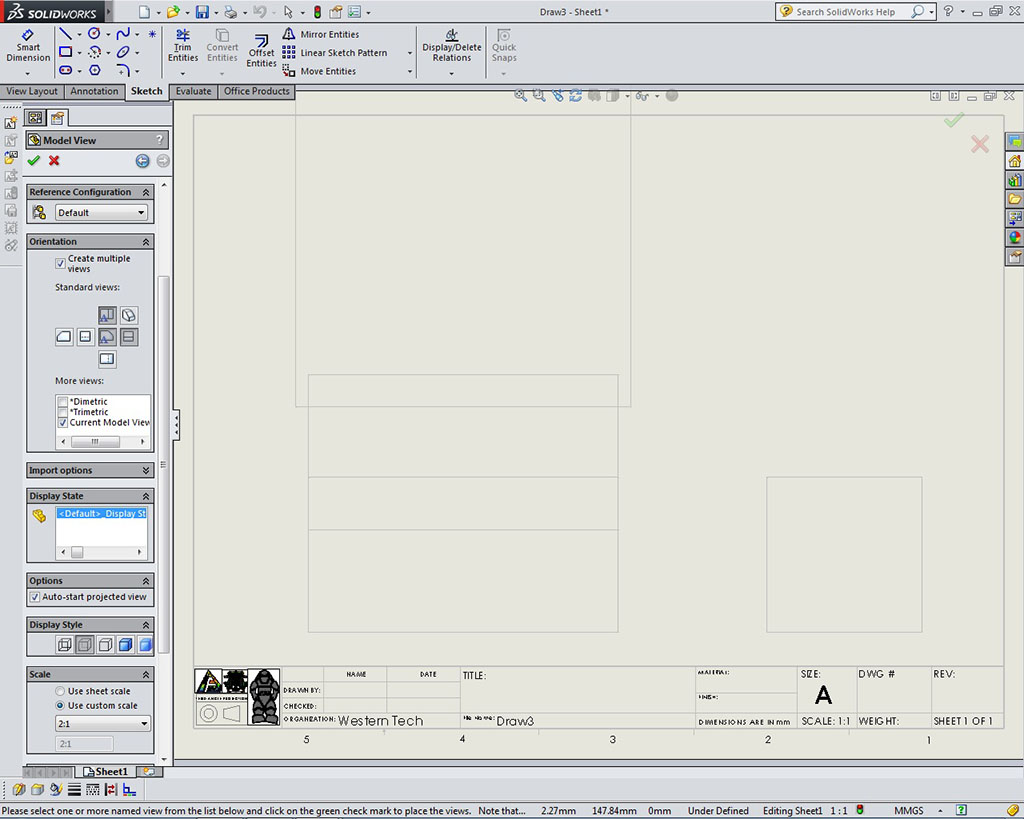
- Multi Views: (on View Layout tab - more options bringing in model views is available) On the left panel, check off Create multiple views, then select the top, front, and right side views. Also in the More views, check off Current Model View - which should be the the best ISO view. Under Display Style, check off the hidden lines view style. Once you have selected all of your options click on the green check mark to complete. You will want to adjust the sheet scale under Properties to properly sett the scale. I tried 2:1 as 1:1 is a little small, but later refined to 1.5:1 for a better fit. On a side note here, when you first draw your object, it must be drawn keeping in mind the program will automatically use that to select views here. It may be possible to move to another plane, or change the plane, and change the default orientation view depending on your situation
- Views Loaded: You may want to re-adjust a number of settings for each of the views such as scale, hidden lines, etc. for example if needed
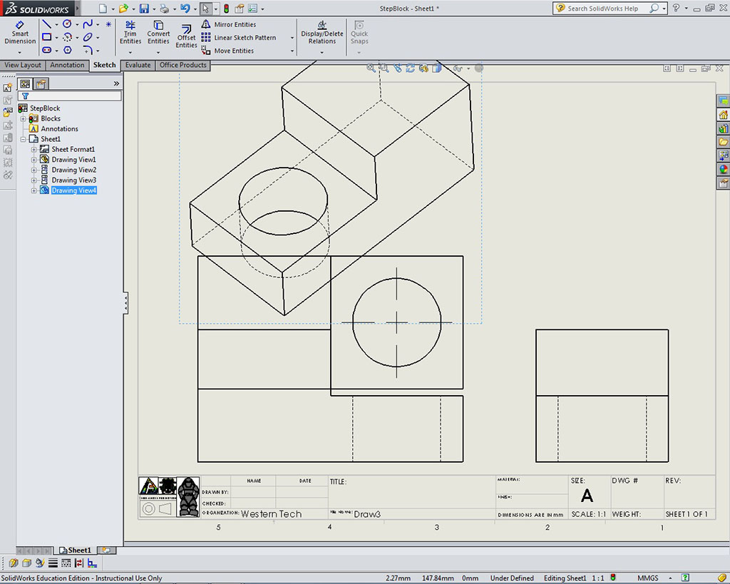
- Views Placed: Adjust view spacing and locations with equal spacing between the top, front, and side views and ensure drawing view envelope is centred on page with maximum paper space being used
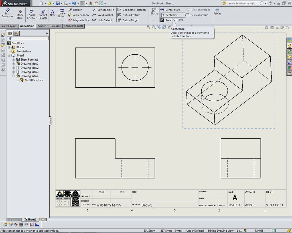
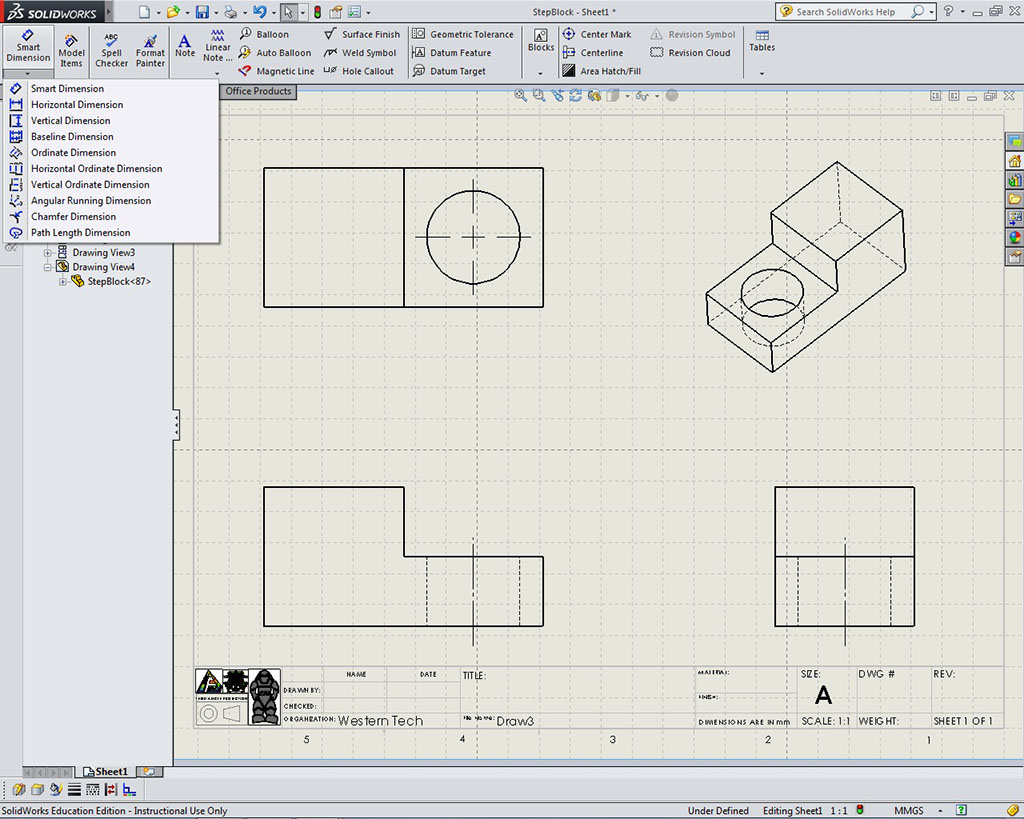
- Centre Lines: Select Annotation tab to get access to the centre line tool, and select to add centre lines to the appropriate views
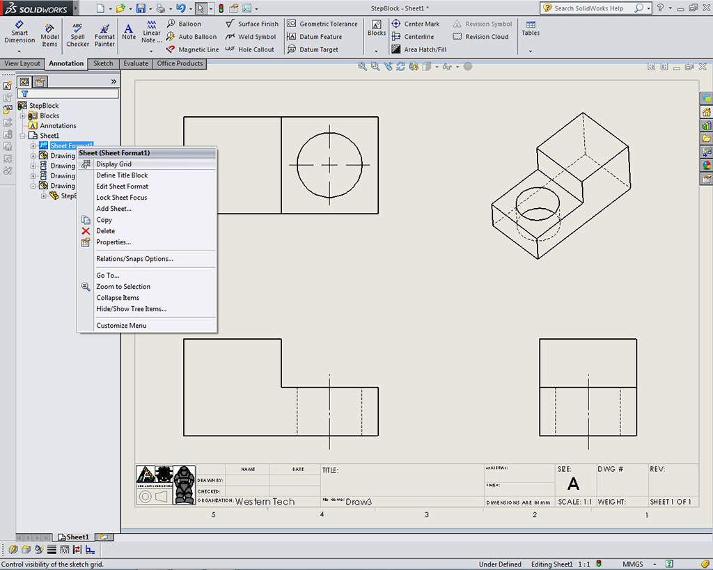
- Turn Grid on: Using menu in feature tree click on sheet format and click on display grid. This will help with final dimension placement and organization.
- Grid on: Before dimensioning your object views, with the grid turned on, will help with dimension placement, spacing, and organization. More adjustments to grid can be modified in the Options, under Document: Grid section.
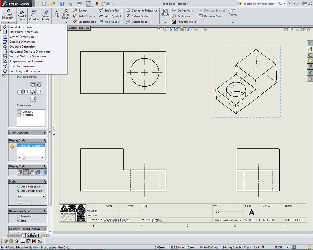
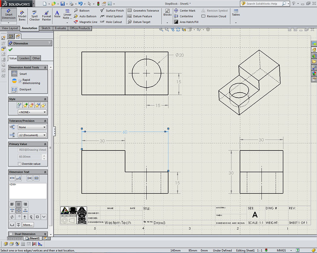
- Dimensions: Using menu Insert >Model Items,(or use top panel model insert icon tool) will pull in dimensions from sketch and features (Black colour auto vs grey for manually created), then straighten out keeping in mind overall and detail dimension standards (SHIFT can move dimensions from one view to the other while CTRL will copy). For manual adding of dimensions (gray colour), the Smart Dimension tool will accommodate most needs. Remember always place dimensions in the view that best shows the feature/detail the most
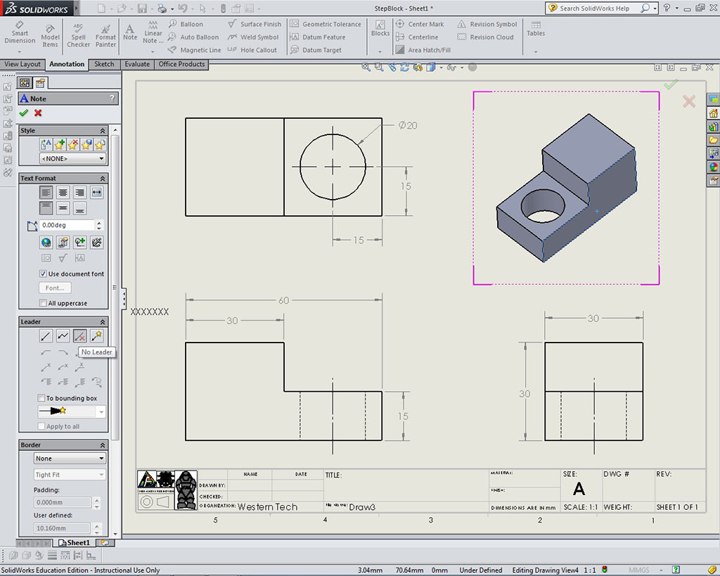
- ISO Shading: Note the ISO has been scaled a little smaller and leaned correctly for better spacing, best view, and fit. Select ISO and in the left properties panel, change the Display Style to shaded with outline, then right click sub menu and select "Add View Label" to put the scaled view of the ISO you just placed (note: not shown in example below)
- Note-No Leader: With the Note tool selected in the left properties panel, in the Leader window, select No Leader icon and note other options and changes that are possible here
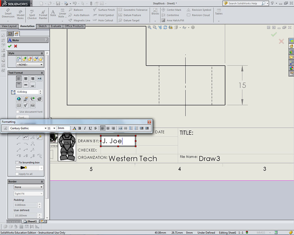
- Fill-in Information: When clicking in a location to make a note to type some text, note the long formating box that pops up with all the options you have. Most of this information should have been filled in with the exception of the sheet scale. If not check your model custom information that was done when creating the model earlier
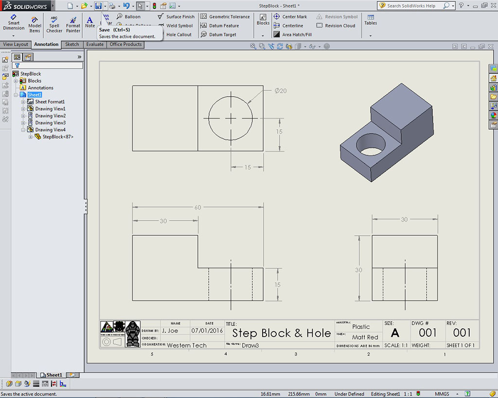
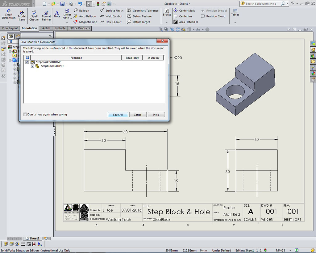
- Information Block Done: Remember, most fields in the information block are filled in automatically from your model custom table information put in when you were working on your model
- Saving: Do not wait till the end to save your file, should be saving every few minutes with the Ctrl s, but at the end save your work with drawing sheet fitted in pages space using the "f" key
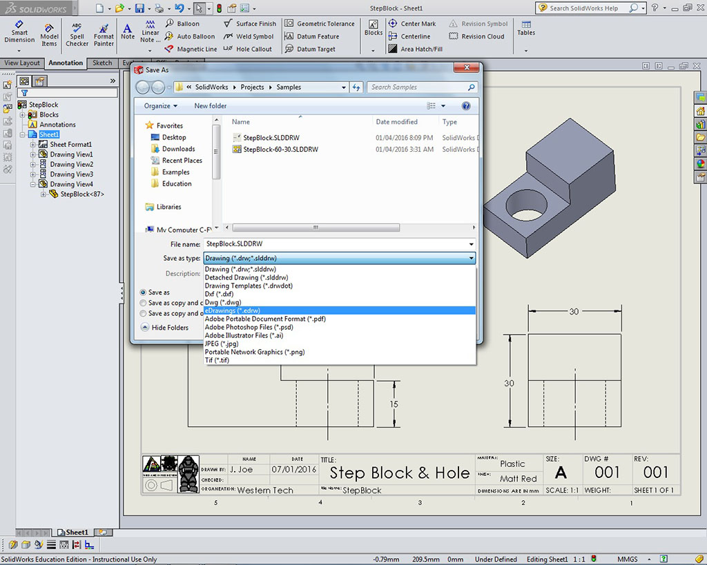
- File Types: Note all the different file types you can save to, using the Save As file command, although we will be concerned with the following file types - proprietary native drawing file extension: SLDDRW, and the compressed standard photo image file type: JPG.
- Hand in the whole folder, with the folder properly named folder example created when you started the Step Block project last activity - previous example was given: You must save your file to your USB flash drive in a folder, for example: td2-1_d-joe_step-block), and all the files inside should have file naming convention td2-1_d-joe_step-block_P_60x30x30mm with appropriate file extensions from both the model and the drawing files. Keep in mind that the jpg of the model should have an _P and for the drawing version have a _D in the file name, otherwise you will overwrite the model files when saving the drawing files as jpg
Step 1
New Drawing
Step 2
Template Selection
Step 3
Multi Views
Step 4
Views Loaded
Step 5
Views Placed
Step 6
Centre Lines
Step 7
Dim Selections
Step 8
Grid On
Step 9
Dimensions

Step 10
ISO Shading
Step 11
Note-No Leader
Step 12
Fill-in Info
Step 13
Info Block Done
Step 14
Saving
Step 15
File Types
Creating Your Key Ring Accessory Drawing
After successfully creating the step block drawing exercise and feel you understand the process, start on your key ring accessory drawing. You should review your mark and feedback from your Step Block project once handed back. Ensure you have all your overall dimensions and the appropriate amount of detail dimensions, and that they are in the right locations. Any circular object features, use the centre lines to dimension with. KRA to be also handed in with the model, drawing file with jpgs. Remember to use your peer expert area tool resource pages from the pick-up folder to assist with your KRA design build in SolidWorks.
Evaluation:
You will be evaluated based on the completion of the above steps and your final product design. Remember when you hand in both your Step Block and your Key Ring Accessory projects to hand in only after you have completed and handed in the Solidworks Self/Peer Checklist sheet. This self/peer evaluation sheets is there to help you hand in the best product and get you written feedback on your completed work. This self/peer evaluation sheet (worth 10% of project mark) is there to help you hand in the best product and get written feedback on your completed work.

| Evaluation Breakdown Component Descriptions | Marks |
|---|---|
| Always double check that you have completed all components for full marks. | |
| Ortho Step Block Model/DWG - Self/peer eval and digital folder/files | 30 |
| Ortho KRA Model/DWG - Self/peer eval and digital folder/files | 40 |
Unit 4, Act. 3: Printing Model in 3D
Situation:
Having a 3D printer gives students the ability to see their design go from a virtual 3D version to a physical hand-held object. It is at this point that a lot of students will realize the power of what a designer has in Technological Design, and what Engineers experience when they see their design being built.
Problem/Challenge:
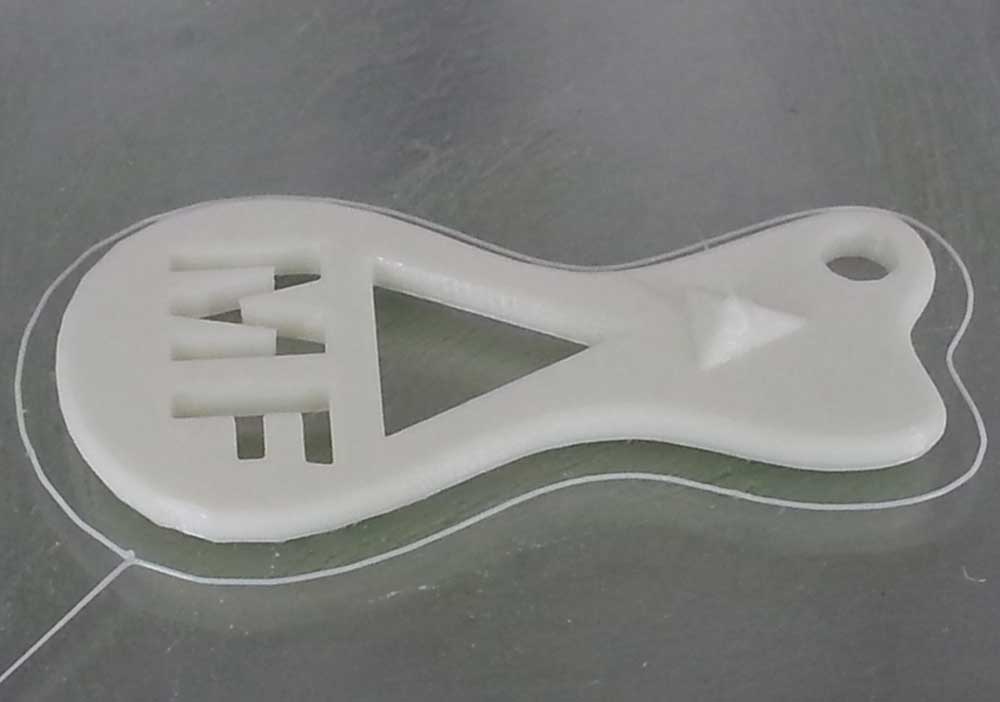
You will take your keyring accessory design and print it using the 3D printer. By using an exported STL file with the Cura application, select best plane/direction your design must sit on the pad, to maximize printing quality. Explore tools and view options, then re-save your STL file as an AMF and a GCODE file and print your file using the Ultimaker 2. You will print two at the same time and take a picture of your finished product to submit. The second printed design will be used for as a display sample.
Investigation/Ideas:

3D Printing
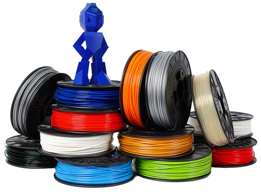
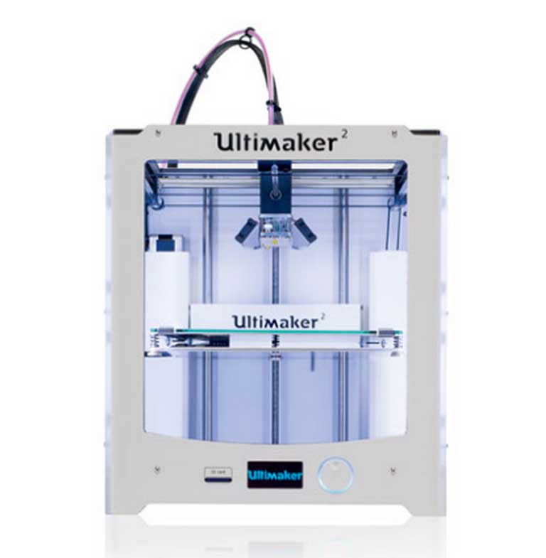
Printing in 3D is relatively new, last 10 years, and is now more common today to find a lot of hobbyist to have these in their home. The market is still expanding and new technologies, methods, and types of printers and print material is in constant flux. For this reason you can see a wide range of types and sizes out there. Ultimaker 2 is one printer that has been rated one of the best on the market for it size and use in a consumer environment.
3D Related Resources
- What is 3D printing?
- Beginners Guide
- ULTIMAKER 2 series
- Ultimaker 2 3D Printer review
- Ultimaker2 User Manual
- CURA software
- History of 3D Printing
- What Is 3D Printing?, (2.21)
- GIANT 3D Printers!, (3.46)
- Cleaning the nozzle, 1.39
Just like you learned how to sketch the step block either by additive or subtractive methods, you can see the similarities with 3D printing vs machining. Looking at the process of 3D printing, you can observe that this is a "additive technology" meaning when making/creating a part it adds material to build the part. The opposite is true with to today's machining process, which creates parts by taking material away and can be looked at as a "subtractive technology".
3D Printing Process
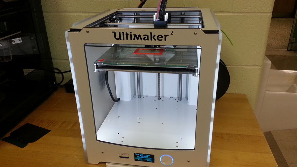
With the Ultimaker 2 3D printer, you will be able to print your design in 3D. It does this by melting plastic it draws from a roll through a plastic tube into a heating chamber that melts the plastic and the head is controlled by an x/y axis bars and servo motors which the printers controller runs based on the G-CODE of that object . Each layer is controlled by the Z axis, A little history and general information can be found here. Settings and maintenance can be found in the ![]() Ultimaker2 User Manual.
Ultimaker2 User Manual.
You will need save a copy of your part file (instructor checked design) as an STL file in SolidWorks. Using conversion software from Cura you will be able to build a AMF and GCODE print file from your exported standard STL file. It is important to place your digital object on the pad in Cura for best possible print. Both files are saved onto the SD flash card and then inserted into the Ultimaker 2 SD slot, The Ultimaker 2 glass base should be cleaned with a wet paper towel or similar, dry wiped clean, and then rub printing area with a glue stick to insure the plastic sticks to the glass base when printing. Here are some of the basic specs:
Price: ` $2500
Dimensions: 14.1 x 13.5 x 15.3 inches
Build volume: 9.1 x 8.9 x 8.1 inches
Filament: 2.85mm
Print speed: 30mm - 300mm/second
Software package: Cura
File types: STL/OBJ/DAE/AMF
Supports: Windows, Ubuntu Linux, Mac OS X
Connects with: USB, WiFi, SD card
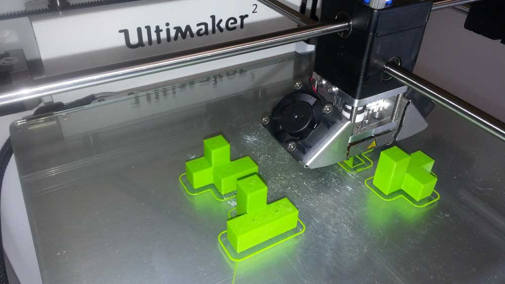
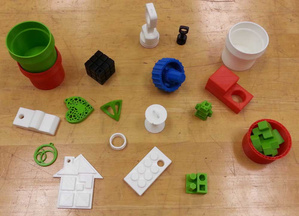
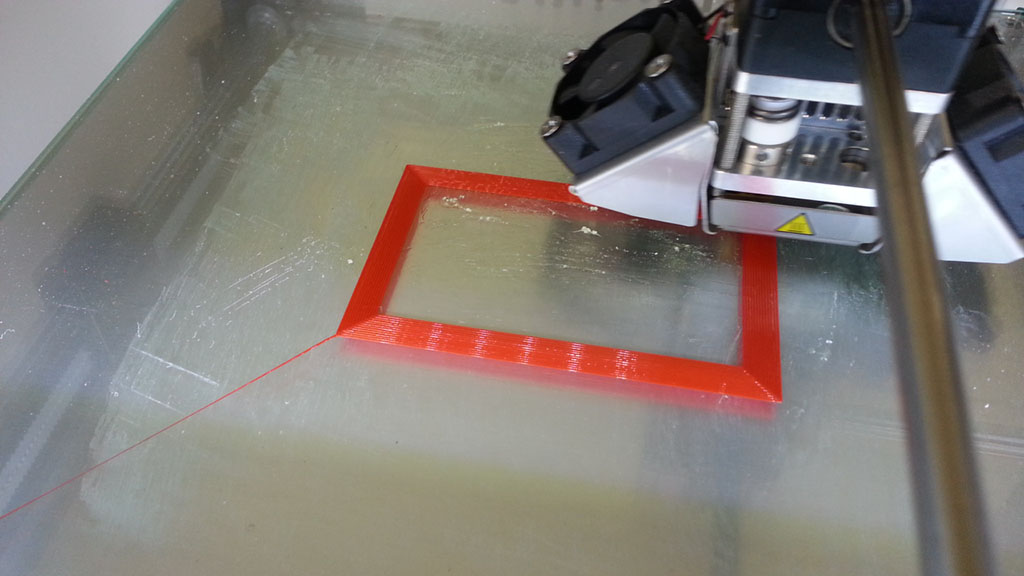
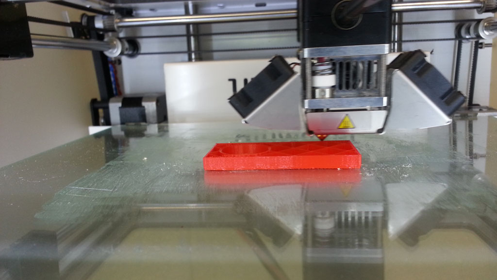
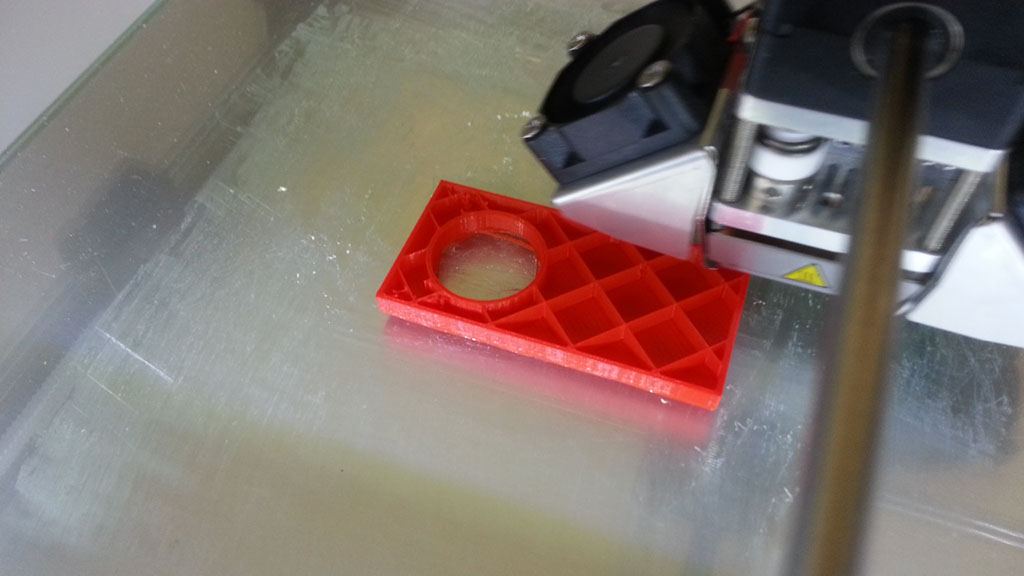
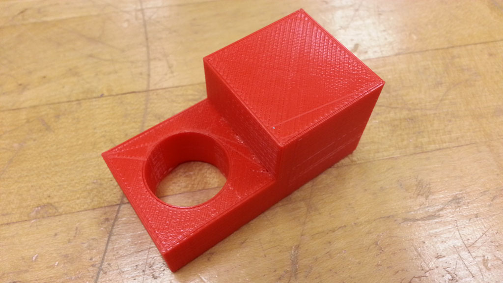
Sample Pictures
Below are some pictures of our Ultimaker 2 printing in action with some recent prints.
Sample 1
Sample 2
Sample 3
Sample 4

Sample 5
Interesting 3D Printer FAQ's:
- Can be used with any CAD program that has the ability to export .STL files
- Supports several thermoplastic materials with two of the most common: PLA and ABS
- PLA is the easiest material to work with and is considered a biodegradable thermoplastic that has been made from renewable resources such as corn starch and sugar cane. It is a preferred choice for support material, but will go brittle when exposed to sun and air in a short time, and is for this reason we will not normally be using it.
- ABS is the second easiest material to work with and is an engineering polymer commonly used to produce car bumpers due to its toughness and strength. It does however have a tendency to warp on larger geometries but is very stable in not going brittle like PLA
- Support material is used to make scaffolding in low resolution to support the geometry of a model which otherwise would be printed in mid-air, can be removed by simply breaking it away/off of your printed part and then sanding or filing to finish off.
- Finish surface quality depends on the geometry and layer thickness you are printing. For example the 0.125mm layer thickness will result in a smoother surface compared with the 0.25mm layer thickness, however it will take longer to print.
Create/Construct:

3D Model to 3D Print Process
You will need your STL file from your key ring accessory prior to creating the G-CODE file using Cura. Use the following steps to print your 3D key ring accessory:
- Printer upgrades Ignore: Nothing to upgrade, just bypass this by selecting Finish
- Select Ultimaker 2: Start the Cura application. If this is the first time running it you will see a configuration wizard window. Select Ultimaker 2 for the printer unit and click Next
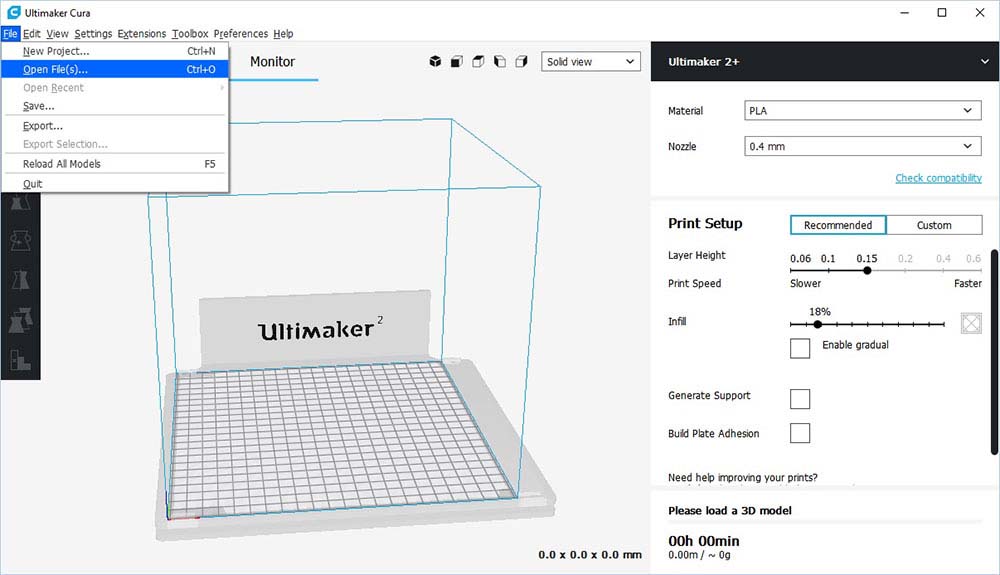
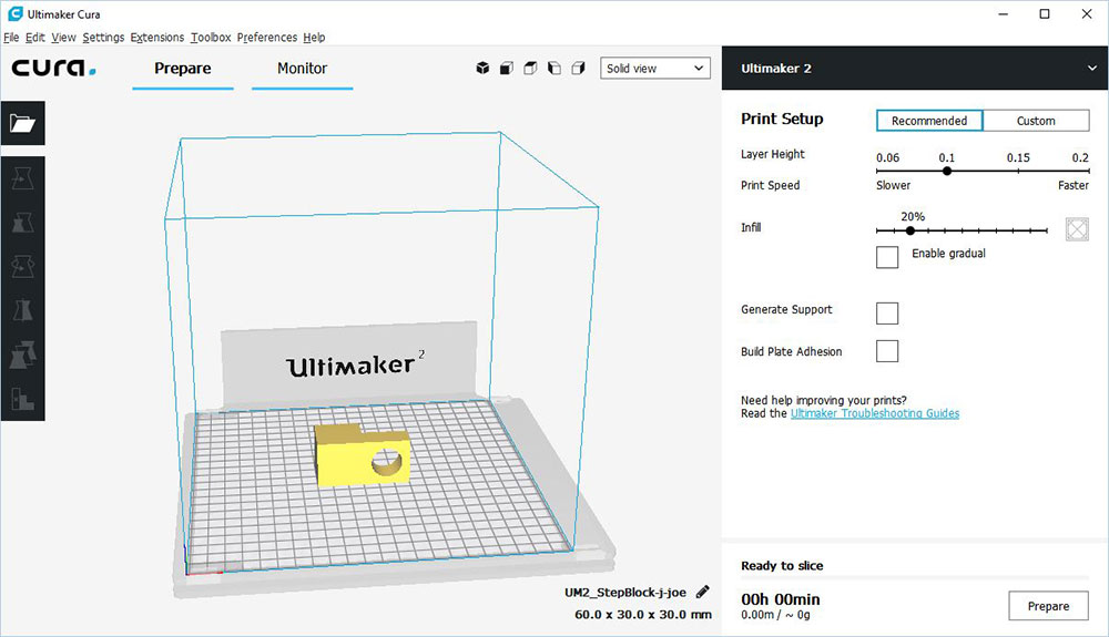
- Application layout:Click on File menu, and select Load Model File, and use the window to select and load your STL model part. At this stage you may need to rotate clicking the rotate tool icon in the lower left corner, which will activate the X, Y, and Z rotate circles. Just drag your object to rotate to a better print setting, for example the step block hole is better printed with the centre perpendicular to the platform
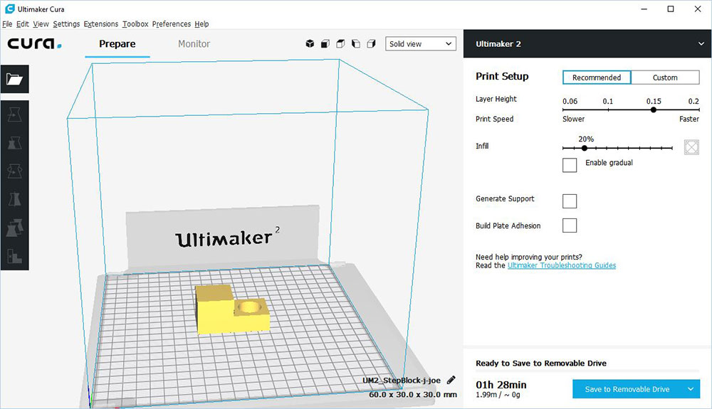
- Settings: Set layer height to 0.15 with infill at 20% with support and build plate adhesion (normally... check with instructor for your situation) checked and gradual fill off. Certain situations may require different settings.
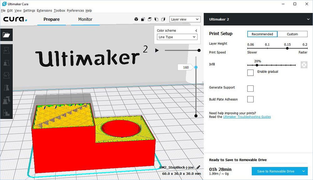
- Layer Build View: This view shows an example of halfway through the print and if you look closely you will see the web framed internal design
- Save G-Code: Saving the G-CODE is what the Ultimaker 2 will use to print your object, name file using short file naming convention, ex: td2_d-joe_sb.GCODE, then save. Note if you make changes to your STL file while in Cura, you should also save those changes in a .3mf project file, or the next time you print, you will have to redo the set-up
- SD Card adapter: You need the adapter and the SD card from Ultimaker to transfer the files (GCODE and STL) on to SD card, then put back into Ultimaker SD slot, For efficient time savings, printing multiple objects at once is a better option, but if something should go wrong, the whole (long print) will have to be re-started
- Control Panel: Rotary dial is used to select Print, then you rotate to find your G-CODE file which will show the print time and amount of filament plastic will be used, press the rotary button to start print. Heated glass platform should be cleaned using a little bit of water and paper towel if needed
- If your print is challenging with its base, you may need to put some glue down from glue stick to ensure print sticks to the platform
- After starting the print, the print head heats up for about a minute, then will start printing
- You need to watch and make sure first layer prints correctly, if not, you will need to abort print and try again after checking filament feed
- Half way through you can see the glue on the glass and the small print head with a servo motor to the left which drives the track/rails
- Part way though the print you can see the web frame structure inside the object print, i.e. objects are not printed with solid plastic as this would take a lot longer and use more material
- Print Finished: You will need to use a thin scrapper to work object off of glass platform once it has had a chance to cool down
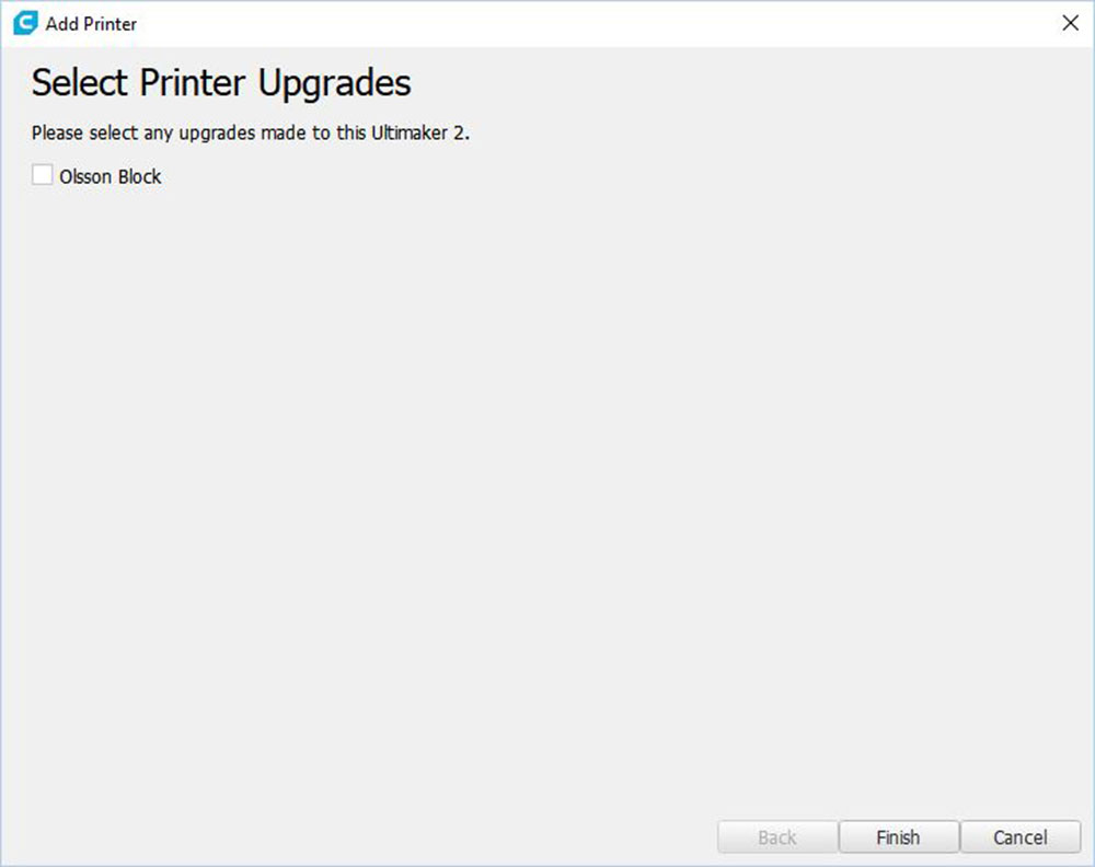
No upgrades
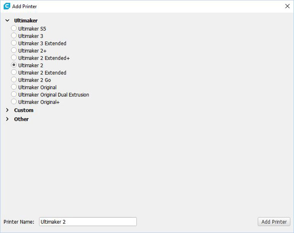
Add printer

Ultimaker 2
Application

Open STL
STL Opened

Rotate tool
Placement
Preview

Control Panel

Printing Started
First Layer
Half Way
Inside support
Print Finished
Remember to take some pictures of the 3D printing process to use in your design wiki page.
Evaluation:
You need to make sure you have followed all steps through this process. You will need to clean up your printed object using a file and/or sandpaper. Evaluation is based on your process and final design handed in, in the appropriate files and formats.
You will be evaluated based on the completion of the above 10 steps and your final product design.

| Evaluation Breakdown Component Descriptions | Marks |
|---|---|
| Always double check that you have completed all components for full marks. | |
| Key Ring Accessory - successfully 3D printed x2 | 20 |