Unit 2 Introduction to Basic Software Drawing Tools
This unit will introduce you to some software drawing tools that can be used in technical design challenges. This will prepare you to work with more complex drawing programs and use these software drawing tools in the design process to support and accelerate virtual design problems.
Unit Content Activity Quick Links, Click to Jump to Specific Activity!
- Unit 2, Act. 1: Introduction to 2D Drawing - DraftSight
- Unit 2, Act. 2: Introduction to 3D Drawing - Google SketchUp
 Unit 2, Act. 1: Introduction to 2D Drawing - DraftSight
Situation:
Having now learned about sketching, orthographic and isometric drawings, it is easy for you to communicate effectively with pencil and paper throughout the technology design process. With the advancement of computers and software applications, it has helped people today get things done faster, more efficient, and more organized. It has also saved on the environment in many ways including paper saving. Drawing programs have come a long way in the last 15 years and it is a great way to not only communicate, but also modify and update your ideas very easily.
Problem/Challenge:
Using the recent orthographic sketch of the step block, redraw using absolute coordinate system to draw the three views and use a new layer to draw the hidden lines in the appropriate views. Spacing is to be 40 mm between objects and at the using the text tool write in your project information prior to handing in, in the form of the program's proprietary file format dwg and export also as a pdf.
Investigation/Ideas:
DraftSight is a 2D drawing program that can accurately draw objects using simple commands. This type of program is commonly used in a variety of fields where layout drawing plans are needed to communicate a lot of information graphically. Before starting to draw your step block, explore the program, experiment with different tools and familiarize yourself with the applications interface, as it is similar to programs used in industry.
You can download a PDF in-depth guide to Getting Started if you want more information on the operation, tools, and interface.. This is a free program you can download and instal on your system. While working, save your work to your USB flash stick and always backup to your H drive at school or your home computer.
Create/Construct:
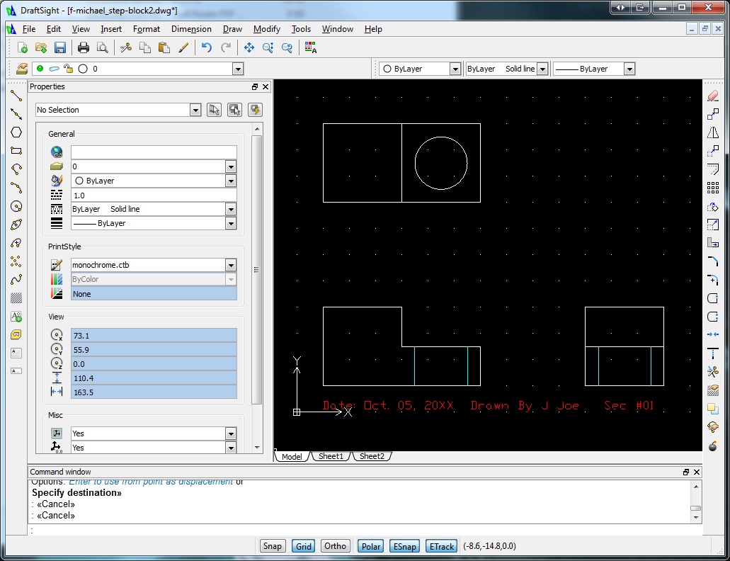
Using the 2D CAD program called DraftSight, create an ortho of the step block as in our final sketch above, using the following brief steps from the demonstration:
- Open to standard template
- Type in Units, change decimal to 1 place holder, change block units to mm
- Turn grid on with grid button at the bottom
- Type in Limits, then enter for default "0,0" and then "150,120"
- Type in Grid, and then type 10 to change the grid density
- Type "z" for zoom, then "e" for extents, to show the whole workspace
- Use the poly line tool and enter Absolute coordinates "10,10" (x,y) as your starting point
- Continue to enter the rest of the coordinates to finish the ortho step block front view.
- Using the layer commands, make a text layer and change colour to red
- Using the note tool, put the date, your name, your section at the bottom
- Create anotherlayer - Hidden with dashed blue lines for your hidden features
- Save in DWG and also export to PDF file format when handing in.
Sample 2D
Step Block
Ensure the file extensions are correct and present. Here are some examples of file names you should be using:
- DraftSight program file name example: d-joe_2Dstepblock.dwg
- PDF - Portable File Document file name example: d-joe_2Dstepblock.pdf
Evaluation:
Evaluation points
| Evaluation Breakdown Component Descriptions | Marks |
|---|---|
| Always double check that you have completed all components for full marks. | |
| Accuracy - file set-up, grid spacing, object sizes and features correctly drawn | 5 |
| Location - all views drawn with 40 mm spacing and in the right locations | 5 |
| Final drawing - correct lines, layers, text, saved in dwg and pdf formats | 5 |
Unit 2, Act. 2: Introduction to 3D Drawing - Google SketchUp
Situation:
Learning to draw and design with different technical drawing programs is a great way to communicate your ideas accurately and can easily be modified to future needs. As a technical design student this can be a very helpful tool with the design process.
Problem/Challenge:
You are to accurately draw the step block we sketched in class and in the previous application DraftSight. Dimensions are also to be added in a neat organized manner showing all overall dimensions and detail dimensions. Finished file to be handed in with the proprietary file format extension and also as a jpg.
Investigation/Ideas:
Google Sketchup is a free program and has a lot of support on the internet including forums, part database, and tutorials. This program is closely used with Google Earth to build and show 3D buildings on it's maps. This program application has many setup configurations to allow different types of drawings and standards.
Extra help/resources can be found here if you need more information. This is a free program you can download here and instal on your system.
Create/Construct:
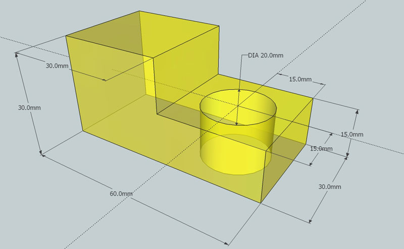
Here is a list of the major steps that were show during the class demonstration, and a final 3D drawing sample that you can follow if you need extra support:
- Select template: Product Design and Woodworking Millimeters
- Draw a rectangle using the Rectangle tool, type the exact height, press enter
- Use the zoom extents icon to re-size, re-draw and center your object at any time
- Use the push/pull tool to pull up the object up, type the exact height, press enter
- Finish the rest of the block using the same tools/process
- Tip: use the tape measure to find centre for hole.
- Create/show dimensions by selecting the menu tools, and dimensioning
- Show overall and detail dimensions
- Save in proper file format in two file types: SKP and JPG formats
- Use File > Export > 2D Graphics for creating the JPG
- Tip: ensure view is centred and full screen prior to exporting to jpg
Sample 3D
Step Block
When you are finished check with two peers to ensure you have completed the tutorial correctly. When handing in any files, you will submit it in the student share hand-in-folder as discussed in class, in the proprietary program file format extension skp and also export to a jpg format. Ensure the file extension is correct and present. Here are some examples of file name you should be using:
- Google Sketchup file name example: d-joe_3Dstepblock.skp
- JPG - Joint Photographic Experts Group file name example: d-joe_3Dstepblock.jpg
Evaluation:
The chart below will show the breakdown on each of the assignments and project components building up to the final key chain.
| Evaluation Breakdown Component Descriptions | Marks |
|---|---|
| Always double check that you have completed all components for full marks. | |
| Accuracy - file set-up, object sizes and features correctly drawn | 5 |
| Dimensions - all overall and necessary detail dimensions neatly located | 5 |
| Final drawing - circle center lines, overall look, saved in skp and jpg formats | 5 |